An engineer who has spent a career building conventional hydropower dams and moves to a pumped storage project will find that the concrete looks the same but behaves in a fundamentally different environment.
A conventional dam impounds a river. The reservoir fills gradually, reaches its design level, and operates within a narrow band of seasonal variation. The concrete faces a static or slowly changing hydrostatic load. The waterways carry flow in one direction. The thermal regime is stable.
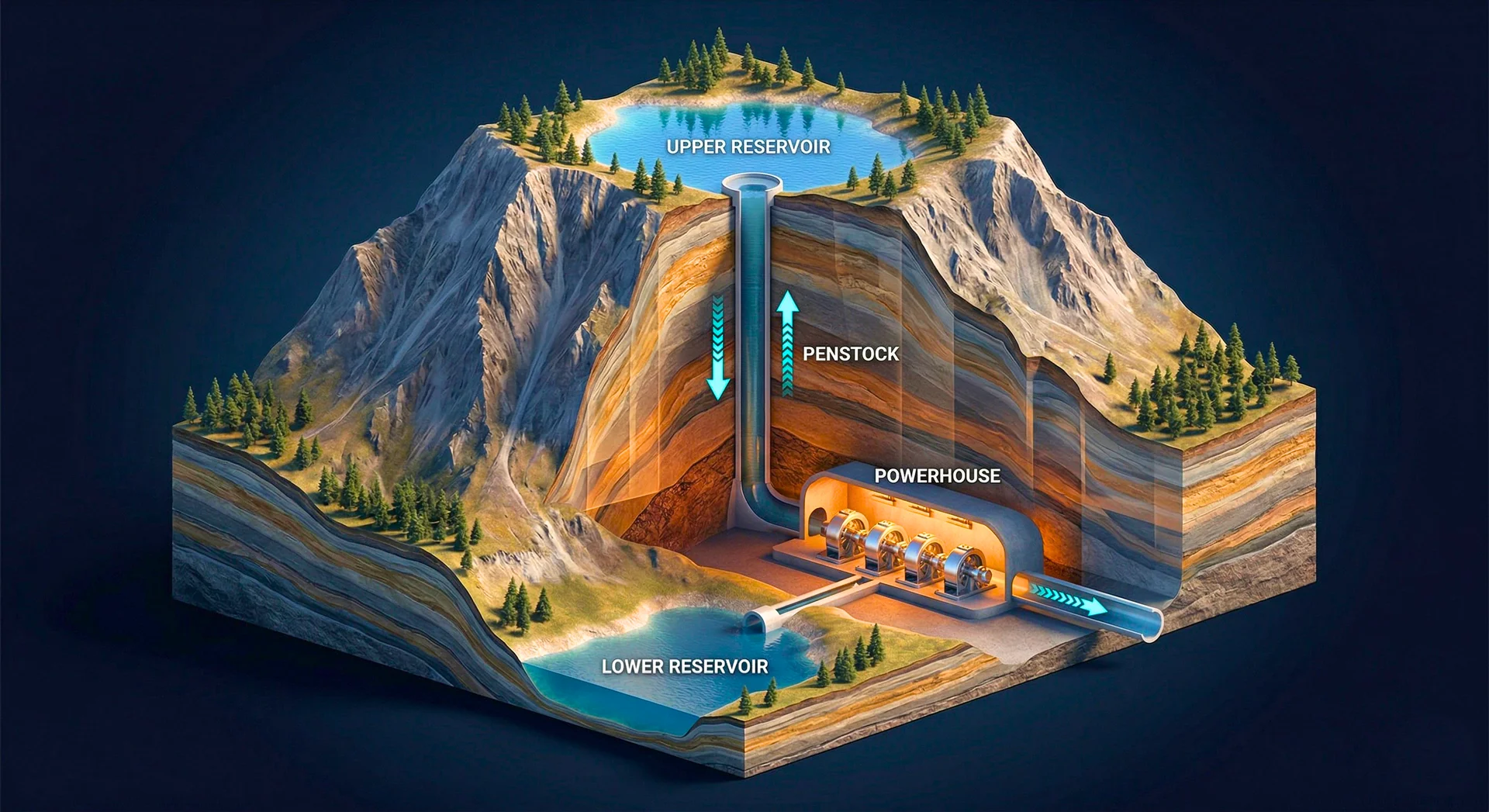
A pumped storage facility stores and releases energy by moving water between two reservoirs at different elevations. Every day, the upper reservoir drops by 10-30 metres as water is released to generate power, then refills as water is pumped back up to store energy. The lower reservoir mirrors this cycle in reverse.
This daily oscillation changes everything about how the concrete performs: the loading regime, the durability demands, the abrasion environment, and the design life considerations. Engineers who carry conventional hydropower assumptions into pumped storage design will underspecify concrete performance for the actual operating conditions.
Difference 1: Cyclic Water Level Fluctuation
Conventional Hydropower
The reservoir level varies seasonally: high after monsoon inflows, low during the dry season. The cycle is annual, with fluctuations typically measured in single-digit metres per month. The concrete on the upstream face and reservoir banks experiences slow changes in hydrostatic load and moisture exposure.
Pumped Storage
The reservoir level varies daily, sometimes multiple times per day. A single operating cycle might involve a 15-25 metre drawdown over 4-8 hours, followed by a 15-25 metre refill over the next 4-8 hours. Over a year, the concrete experiences 365-700+ full loading cycles.
What This Does to Concrete
Research published in ACS Omega documents the progressive degradation of concrete under cyclic immersion-drying:
- Saturated water content increases logarithmically with the number of cycles. Each cycle drives water slightly deeper into the pore structure.
- Ultrasonic pulse velocity decreases by approximately 10% after sustained cycling, indicating microstructural damage accumulation.
- Load-bearing capacity degrades as the repeated moisture cycling weakens the cement paste at the micro level, a primary driver of durability and service-life design for pumped storage structures.
The U.S. Bureau of Reclamation has further established that even at relatively low stress levels, cyclic mechanical loads cause permanent strain to accumulate in concrete. If the cyclic stress is high enough relative to the concrete’s strength, failure can occur at absolute stress levels that would be considered safe under static loading.
For conventional dams, this mechanism is not a design consideration. For pumped storage, it is a primary durability driver.
Design Implications
-
Concrete in the fluctuation zone (the band of dam face between maximum and minimum operating levels) must be designed for cyclic exposure, not static exposure. This means:
- Lower permeability to reduce moisture penetration depth per cycle
- Air entrainment for freeze-thaw resistance (if the site is at altitude, the fluctuation zone may cycle between saturated and frozen)
- Higher abrasion resistance if wave action or sediment is present
- Potential for fatigue-rated design in structural elements within the fluctuation zone
-
Slope stability of reservoir banks deteriorates non-linearly with increasing fluctuation cycles. Rapid drawdown is a recognised slope failure trigger, and in pumped storage, rapid drawdown occurs daily. Concrete slope protection, where used, must be designed for this cyclic loading.
Difference 2: Reversible Flow
Conventional Hydropower
Water enters the intake, flows down the penstock, passes through the turbine, and exits through the tailrace. The flow is unidirectional. The concrete waterways are designed for flow from the reservoir to the downstream discharge.
Pumped Storage
The same waterways carry flow in both directions. During generation, water flows from the upper reservoir down to the powerhouse. During pumping, the same water is pushed back up from the lower reservoir to the upper reservoir. The pump-turbines are reversible, switching between generating and pumping modes.
What This Does to Concrete Waterways
Cavitation Reversible flow creates complex hydraulic conditions, particularly during mode transitions (switching from generating to pumping or vice versa). Pressure transients generate vapour bubbles that collapse against concrete surfaces, causing cavitation erosion. Cavitation is a concern in conventional hydropower (particularly in spillways), but the frequency and severity of cavitation events in pumped storage is higher because of the daily mode switching. ACI guidance on abrasion-erosion (ACI 210R) addresses spillway and stilling-basin conditions, but pumped storage waterways experience both more frequent cavitation events and bidirectional abrasion.
Abrasion from Bidirectional Sediment Transport In Indian rivers, water often carries suspended sediment. In conventional hydropower, sediment flows in one direction and is managed through desilting chambers. In pumped storage, particularly open-loop systems that draw from a sediment-carrying river, the same sediment is cycled back and forth through the waterways. Each pass abrades the concrete lining.
Closed-loop (off-stream) pumped storage systems avoid this problem because the water is contained in dedicated reservoirs with minimal sediment input. This is one of several reasons India is increasingly favouring closed-loop designs.
Pressure Cycling in Surge Shafts Surge shafts manage pressure transients during load changes. In conventional hydropower, load changes occur during start-up, shutdown, and load following. In pumped storage, the most severe transient occurs during mode switching: the entire flow reverses direction, and the surge shaft must absorb the resulting water hammer. This subjects the concrete surge shaft lining to cyclic pressure loading at higher frequency and amplitude than conventional hydropower.
Design Implications
- Tunnel and penstock linings must be designed for pressure loading in both directions, with fatigue considerations for the mode-switching transients
- Concrete in high-velocity zones must achieve HPC-grade abrasion resistance, or be protected by specialised coatings (polyurethane, epoxy, cermet)
- Surge shaft concrete must resist cyclic tensile stress from pressure waves, requiring higher reinforcement ratios or fibre reinforcement compared to conventional surge shafts
- GF-reinforced concrete (glass fibre-reinforced) is increasingly specified for flow channel surfaces where both abrasion and flexural stress are present
Difference 3: Twin Reservoir Construction
Conventional Hydropower
One dam. One reservoir (the river valley). The river itself provides the storage volume.
Pumped Storage
Two reservoirs at different elevations. In an open-loop system, the lower reservoir is often an existing river or lake. In a closed-loop (off-stream) system, both reservoirs are purpose-built, requiring construction of two dams and two storage impoundments.
Construction Implications
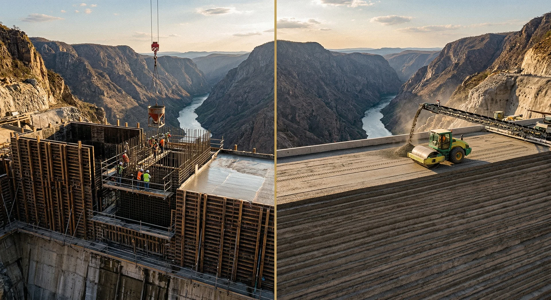
Double the dam concrete. The most obvious implication. A closed-loop pumped storage project builds two dams: one for the upper reservoir and one for the lower reservoir. Each dam requires its own foundation treatment, concrete production, thermal control, and quality programme.
The upper reservoir is the harder build. The upper reservoir is typically at a higher elevation, often in more rugged and remote terrain. Access roads may need to be constructed. Material transport is more difficult. The construction season may be shorter. The geology may be less favourable (ridgeline sites versus valley-floor sites).
For projects like Kundah PSP (approximately 2,400 metres elevation in the Nilgiri Hills), the upper reservoir construction faces high-altitude logistics challenges that the lower reservoir does not.
Reservoir lining is a novel challenge. Conventional dam reservoirs are natural river valleys. The reservoir floor and banks are geological formations. Pumped storage reservoirs, particularly constructed upper reservoirs, may require engineered lining to prevent seepage losses. The lining must withstand daily water level cycling, a condition for which standard reservoir lining guidelines from ICOLD and national agencies were not designed.
Options include:
- Dense asphalt concrete (DAC): Proven in European pumped storage projects. Flexible, impermeable, and tolerant of some differential settlement. But expensive and requires specialised equipment.
- Reinforced concrete slabs: Durable but vulnerable to cracking under cyclic loading and differential settlement.
- Geomembrane: Lightweight and impermeable, but vulnerable to mechanical damage, UV degradation, and puncture from wave action or debris.
- Concrete-faced rockfill: The concrete face provides waterproofing on a rockfill body. Used at Pinnapuram (1,680 MW) and many international projects.
Difference 4: Underground Structures at Scale
Conventional Hydropower
Many conventional projects are surface powerhouses or small underground caverns. The tunnel system is limited to the headrace and tailrace.
Pumped Storage
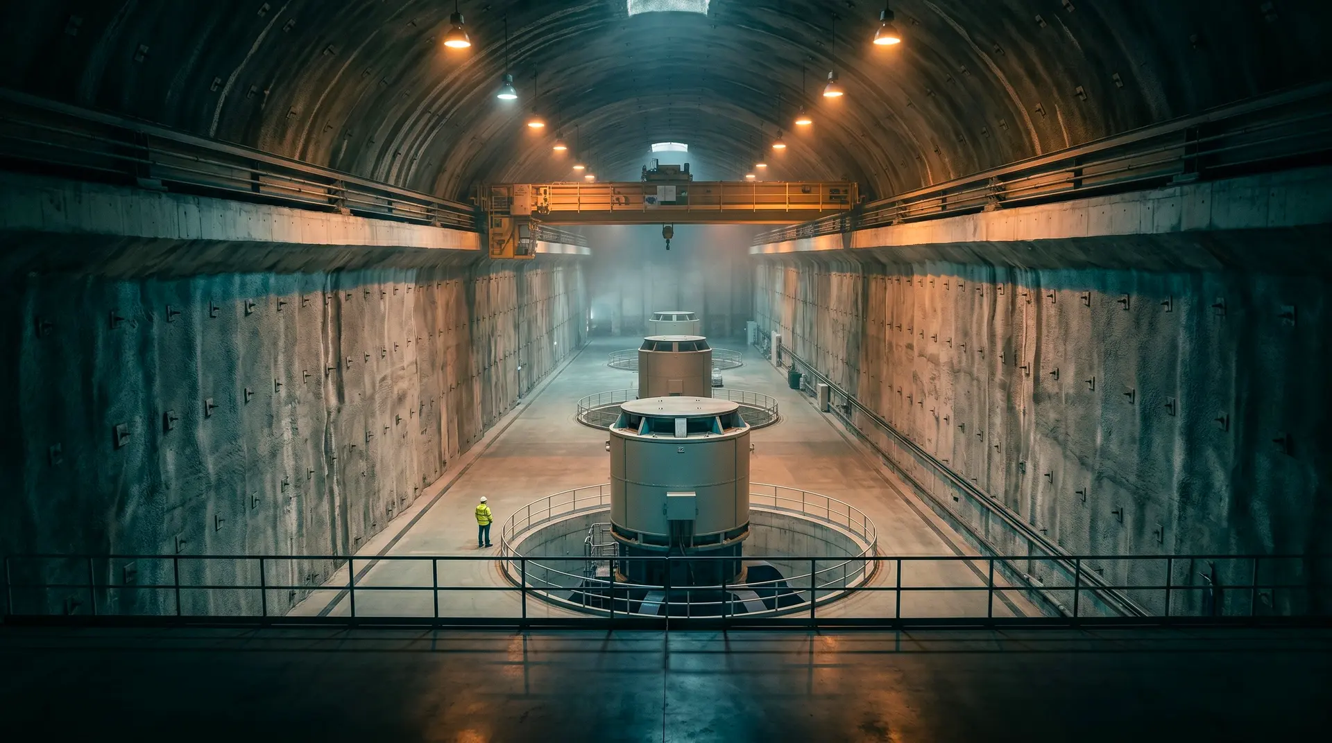
Pumped storage projects typically have larger underground caverns (to house reversible pump-turbines, which are larger than conventional turbines) and more complex tunnel systems (headrace, tailrace, surge shafts in both directions, access tunnels, cable tunnels).
Tehri PSP’s underground machine hall measures 203 metres long, 28.2 metres wide, and 56 metres high. Pinnapuram’s subsurface powerhouse is 240 metres long, 24 metres wide, 58 metres high. These are among the largest underground caverns in Indian infrastructure.
Concrete Implications
- Self-compacting concrete (SCC) may be required for complex underground geometries where conventional vibration is not feasible (used at Tehri PSP)
- Shotcrete quality and durability become critical for initial tunnel support across longer tunnel lengths
- Rock-concrete interaction must be designed for squeezing ground conditions, which are common in Himalayan geology (Tehri experienced squeezing rock and mega-shear zones)
- Mass concrete volumes in underground structures require thermal control even though they are below ground (the surrounding rock provides insulation, trapping heat)
Difference 5: Design Life Under Operating Conditions
Conventional Hydropower
A conventional dam’s concrete is designed for 100+ years of essentially static service: resisting a constant hydrostatic load with seasonal variation. The deterioration mechanisms are slow: carbonation, chloride ingress, alkali-aggregate reaction, sulphate attack. All are time-dependent processes under relatively constant conditions.
Pumped Storage
The same concrete is designed for 100+ years, but under radically different service conditions: daily cycling, reversible flow, pressure transients, and accelerated wear. The deterioration mechanisms include everything that affects conventional dams plus cyclic fatigue, accelerated abrasion, cavitation erosion, and progressive degradation from immersion-drying cycles.
The Implication
Pumped storage concrete must be more durable than conventional hydropower concrete for the same design life. The mix design, the surface finishes, the joint treatments, and the QC standards must all be calibrated for an operating environment that is more demanding than any conventional dam will ever experience.
Summary: Where the Differences Matter Most
| Aspect | Conventional Hydropower | Pumped Storage |
|---|---|---|
| Water level cycling | Seasonal (annual) | Daily (365+ cycles/year) |
| Flow direction | Unidirectional | Reversible |
| Cavitation frequency | Occasional (spillway) | Daily (mode switching) |
| Reservoirs to build | 1 (river valley) | 2 (both engineered in closed-loop) |
| Underground scale | Moderate | Large (reversible units are bigger) |
| Surge shaft loading | Moderate transients | Severe cyclic pressure |
| Reservoir lining | Natural valley | Engineered (no standard guidelines) |
| Concrete fatigue | Not a design factor | Primary durability driver |
| Abrasion severity | Moderate | High (bidirectional sediment) |
| Design life complexity | Static service | Cyclic service at 365+ cycles/year |
The concrete for a pumped storage project must do everything conventional dam concrete does, plus survive an operating regime that is 365 times more demanding every year. The engineers, the mix designs, and the quality programmes must be designed for this reality from the first day of the project.