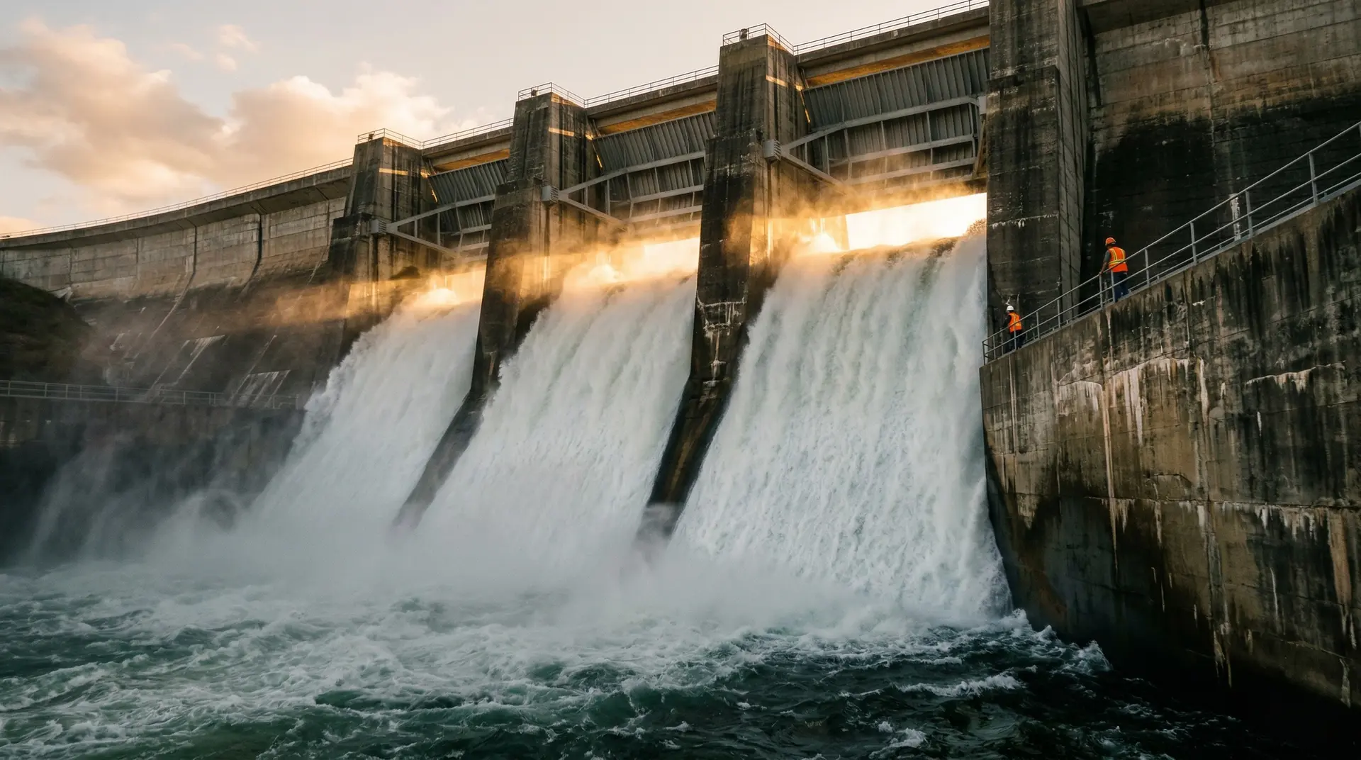
On a monsoon afternoon, the spillway of a large Indian dam operates at full capacity. Water enters the crest at near-zero velocity, accelerates down the chute face to 20-30 metres per second, and crashes into the stilling basin in a violent, turbulent mass of water, air, sediment, and energy.
The concrete beneath this flow is under assault from three directions simultaneously. Suspended sediment grinds the surface like sandpaper. Rocks and debris impact the concrete like projectiles. And at every surface irregularity, every step, every crack edge, water pressure drops below the vapour threshold and cavitation forms: microscopic bubbles that collapse with pressures exceeding 1,000 atmospheres, pitting the concrete surface one shock wave at a time.
This is the operating environment for spillway concrete. It is the most aggressive service condition that any concrete in a dam structure faces, and it continues for every hour of every flood for the life of the dam.
The Tungabhadra Dam gate failure in August 2024 was a public reminder that spillway concrete deterioration has real consequences. After 70+ years of service, the combined effects of abrasion, cavitation, and age-related deterioration compromised the structural integrity of a critical gate component.
The Three Erosion Mechanisms
1. Abrasion
Abrasion is physical wearing of the concrete surface by waterborne particles: sand, silt, gravel, and occasionally rocks. The particles impact the surface at the flow velocity, and the kinetic energy of each impact removes a microscopic amount of cement paste or dislodges an aggregate particle.
Factors that control abrasion severity:
- Flow velocity: Erosion rate increases approximately with the cube of velocity. Doubling velocity increases erosion rate by approximately 8 times.
- Sediment concentration and particle size: Higher concentration and larger particles cause faster erosion. Indian monsoon flows carry particularly high sediment loads.
- Duration of exposure: Total flood hours over the dam’s life determine cumulative wear.
- Concrete quality: Abrasion resistance correlates with compressive strength, aggregate hardness, and paste density. Low-strength concrete erodes faster. Proper mix design is the first line of defence.
Indian context: India’s major rivers, particularly those originating in the Himalayas, carry some of the highest sediment loads in the world. The Brahmaputra, Ganga, and Indus systems transport millions of tonnes of sediment annually. Spillways on these river systems face abrasion intensities that European or North American guidelines may not adequately address.
2. Cavitation
Cavitation is a hydraulic phenomenon where the local water pressure drops below the vapour pressure, causing dissolved gas and water vapour to form bubbles. When these bubbles are carried by the flow into a higher-pressure zone, they collapse violently. The collapse generates a micro-jet of water that strikes the concrete surface at velocities exceeding 100 m/s, with localised pressures exceeding 1,000 atmospheres.
A single bubble collapse removes a negligible amount of material. But millions of collapses per second at the same location can erode through metres of concrete over a few decades.
Where cavitation occurs on spillways:
- Downstream of surface irregularities: A 6 mm step or offset in the concrete surface is enough to cause flow separation and local pressure drop. This is why surface finish quality is critical.
- At changes in profile: The transition from the ogee crest to the chute, the chute to the flip bucket, or any change in slope or curvature.
- At damaged areas: Ironically, areas already damaged by abrasion or previous cavitation become worse cavitation sites because the rough, pitted surface creates more flow disturbance.
The cavitation index (sigma): A dimensionless parameter calculated from the local pressure, vapour pressure, and flow velocity:
σ = (P_local - P_vapour) / (0.5 × ρ × V²)
When σ drops below approximately 0.2-0.3 for concrete surfaces, cavitation damage is likely. Hydraulic engineers calculate σ along the entire spillway profile to identify vulnerable locations.
3. Chemical Dissolution
Soft water (low mineral content) dissolves calcium compounds from the cement paste, progressively increasing the porosity and reducing the surface hardness of the concrete. This mechanism is generally slower than abrasion and cavitation but contributes to long-term surface deterioration, particularly on spillways that operate frequently with relatively clean water.
Designing Spillway Concrete
Concrete Grade and Mix Design
Spillway concrete must be significantly stronger and more durable than the dam body mass concrete:
| Spillway Element | Typical Grade | Key Property | SCM Strategy |
|---|---|---|---|
| Ogee crest | M50-M60 | Abrasion + cavitation resistance | 5-8% silica fume + 20-25% fly ash |
| Chute slab | M45-M55 | Abrasion resistance | 5-8% silica fume + 20-25% fly ash |
| Stilling basin floor | M40-M50 | Impact + abrasion resistance | 5-8% silica fume, consider steel fibre |
| Energy dissipation blocks | M50-M60 | Impact resistance | Steel fibre reinforcement + silica fume |
| Gate slots and sills | M50-M60 | Abrasion + precision | Silica fume, low w/c |
Water-cementitious ratio: 0.35-0.40 for all spillway elements. This is the single most influential mix design parameter for abrasion resistance.
Aggregate: Hard, dense, and abrasion-resistant. The Los Angeles abrasion value should be less than 25% (preferably less than 20%) for spillway aggregates. Soft limestone or weathered aggregate is not acceptable.
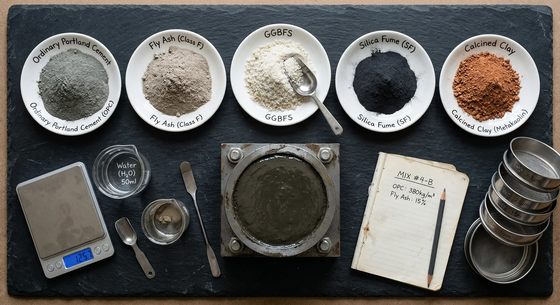
Silica fume: 5-10% of cementitious content. As one of the most effective supplementary cementitious materials, silica fume densifies the paste matrix and improves the paste-aggregate bond, which are the primary mechanisms for abrasion resistance improvement.
Surface Finish
The smoothness of the finished spillway surface directly determines whether cavitation will occur.
Tolerance: The USBR specifies that abrupt surface offsets (steps or misalignments) should not exceed 6 mm, and gradual surface undulations should not exceed 12 mm over a 3-metre length. These tight tolerances require precision formwork and careful finishing.
Why it matters: A 10 mm step in the concrete surface at 20 m/s flow velocity can reduce the local cavitation index below the critical threshold. What appears to be a minor surface defect becomes a cavitation initiation point that progressively damages the concrete.
Aeration
Introducing air into the flow boundary layer is the most effective cavitation prevention measure. An aeration ramp (also called an aerator) creates a region of air-water mixture along the spillway surface where the air bubbles cushion the cavitation collapse, dramatically reducing the erosive impact.
Aeration devices are standard on modern spillways where flow velocities exceed 15-20 m/s and the cavitation index approaches critical values, as documented in ICOLD bulletins on spillway design. The design requires hydraulic analysis to determine the location, size, and air demand of each aerator.
Drainage
Water that penetrates beneath the spillway slab (through joints, cracks, or the concrete matrix) creates uplift pressure that can lift the slab off its foundation. Adequate drainage beneath the spillway slab, through a gravel blanket, drainage pipes, or drilled drain holes, prevents this uplift and ensures the slab remains in contact with the foundation.
Protective Coatings and Overlays
Where the concrete itself cannot provide sufficient resistance, surface coatings and overlays add an additional layer of protection:
Epoxy Coatings
Applied as a thin (1-3 mm) surface layer. Provides good cavitation resistance and moderate abrasion resistance. Service life: 10-20 years depending on exposure. Requires re-application.
Polyurethane Coatings
More flexible than epoxy, with better impact resistance. Used at Almatti Dam for spillway surface repair under DRIP. Service life comparable to epoxy.
Fibre-Reinforced Overlays
A thin (25-50 mm) overlay of steel-fibre or synthetic-fibre reinforced HPC bonded to the existing spillway surface. Provides both abrasion and impact resistance. More durable than coatings but more expensive.
Stainless Steel or Specialty Alloy Armour
For the most severe cavitation zones (spillway crests, flip bucket lips), stainless steel or abrasion-resistant alloy plates anchored to the concrete surface provide the ultimate protection. Expensive but extremely durable.
Inspection and Maintenance
Annual Inspection (Post-Monsoon)
After each flood season, the spillway should be inspected for:
- Surface roughening or aggregate exposure (early abrasion)
- Pitting patterns (cavitation damage)
- Cracking or joint deterioration
- Coating damage or delamination
- Structural damage to energy dissipation elements
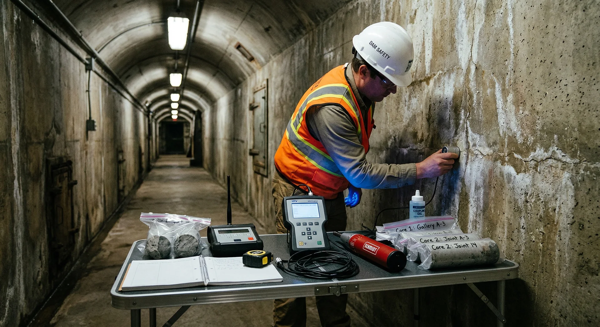
Measurement
Periodic depth measurements at fixed points along the spillway surface (benchmarked from initial as-built surveys) quantify the erosion rate and predict when repair or overlay will be needed. Non-destructive testing methods such as ultrasonic pulse velocity can assess subsurface deterioration beneath the eroded surface.
Repair Timing
The golden rule: repair surface damage before it creates cavitation initiation points. A 10 mm erosion depression that is smoothly contoured causes minimal flow disturbance. The same depression with sharp edges creates a cavitation source that will rapidly deepen the damage.
Early repair of minor surface damage prevents the progressive escalation from abrasion to cavitation to structural erosion.
The Spillway Concrete Specification
For engineers specifying spillway concrete, the minimum specification should include:
- Compressive strength: M45+ (28-day), with 90-day strength as the design basis
- Water-cementitious ratio: Maximum 0.40
- Silica fume: 5-10% of cementitious content
- Aggregate: Los Angeles abrasion value less than 25%, Mohs hardness 6+
- Air content: 4-6% (for freeze-thaw resistance at altitude sites)
- Surface finish: Maximum step 6 mm, maximum undulation 12 mm/3 m
- Curing: Minimum 28 days wet curing for all spillway surfaces
- Abrasion testing: Underwater abrasion test (per ASTM C1138) or Los Angeles machine test on concrete specimens
These requirements are significantly more demanding than mass concrete specifications for the dam body. The spillway specification must be a separate document, not a minor variation of the general concrete specification. A thorough durability assessment should inform every parameter in this specification.
The Bottom Line
A dam’s spillway is its safety valve. When the reservoir rises above the design level, the spillway must pass the flood safely. If the spillway concrete has deteriorated to the point where structural integrity is compromised, the dam cannot safely pass its design flood. That is not a maintenance problem. That is a dam safety problem.
The Tungabhadra failure, the erosion at Hirakud, the deterioration at Almatti: these are not surprises. The Dam Safety Act 2021 now mandates comprehensive safety evaluations that include spillway concrete condition assessment. They are the predictable result of decades of high-velocity, sediment-laden flow acting on concrete surfaces. The engineering response is not to be surprised when spillway concrete wears, but to design it to wear slowly, monitor it regularly, and repair it before the wear becomes structural.
Spillway concrete is the most expensive concrete in a dam per cubic metre. It is also the concrete that earns its cost most directly, because its failure mode is the one with the highest consequence.