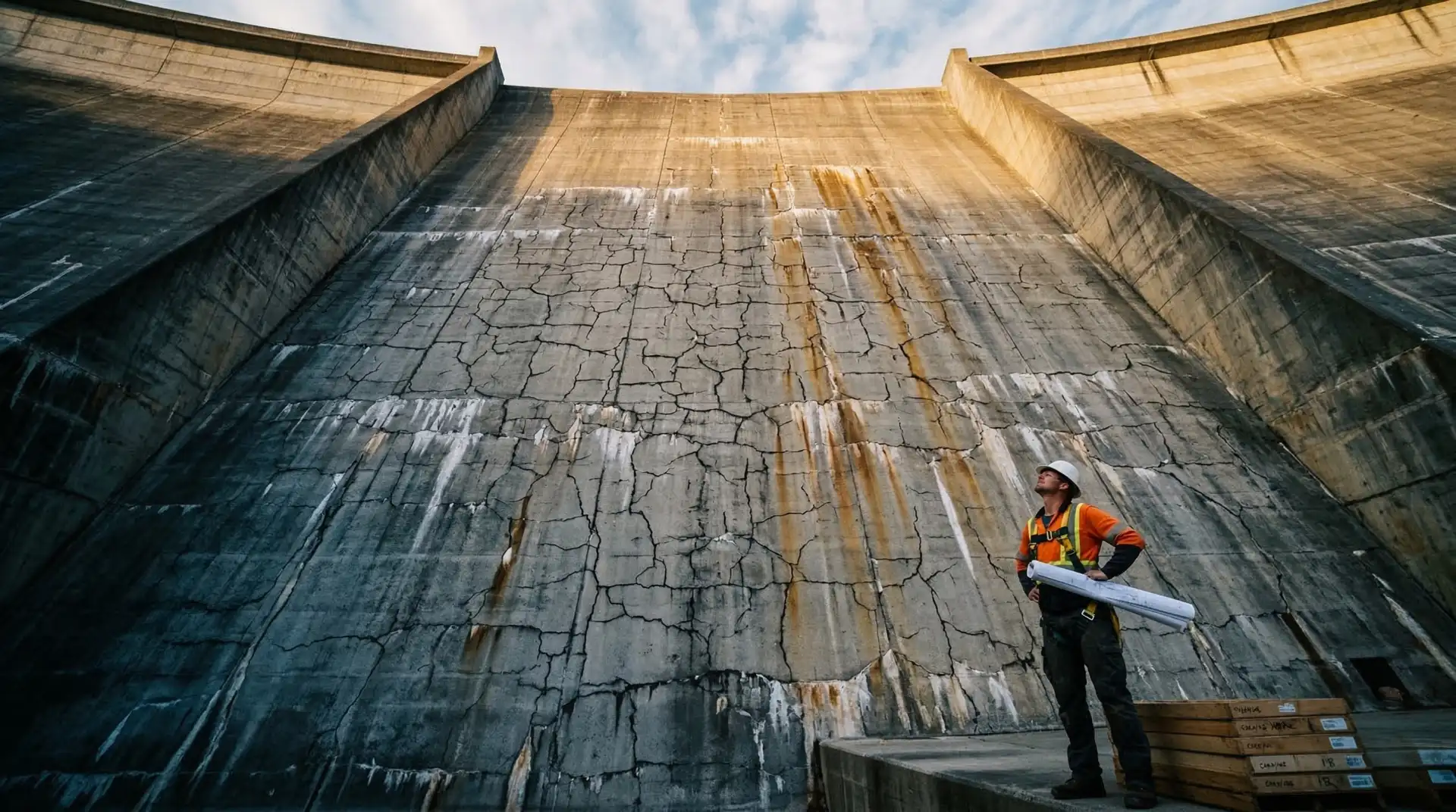
A dam owner looking at a 50-year-old concrete wall sees a surface. What they need to see is what is happening inside.
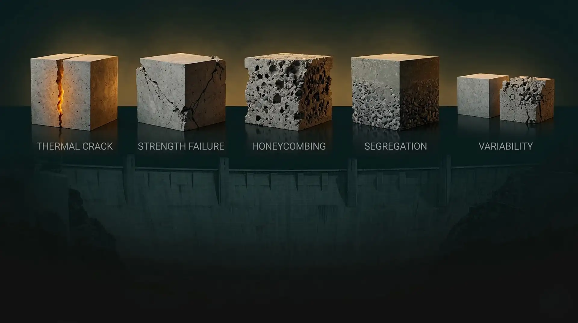
Cracks that have propagated through the core. Alkali-aggregate reaction gel expanding within the aggregate matrix. Voids left by poor consolidation during original construction. Carbonation fronts advancing toward reinforcement. Seepage paths developing along lift joints and monolith joints.
Visual inspection tells you the concrete is deteriorating. Non-destructive testing tells you how bad it is, how deep it goes, and where to focus your investigation.
With the Dam Safety Act 2021 mandating comprehensive safety evaluation of all 6,628 specified dams by December 2026, and 1,681 of those dams already over 50 years old, NDT is no longer optional. It is the foundation of every concrete integrity assessment programme.
Here are the five methods every dam owner should understand.
1. Rebound Hammer (Schmidt Hammer)
What it does: Measures surface hardness of concrete by firing a spring-loaded mass against the surface and measuring the rebound distance. The rebound number correlates with compressive strength.
Indian Standard: IS 13311 Part 2:1992
How it works on a dam: A trained technician places the hammer perpendicular to the concrete surface at predetermined grid points across the dam face, gallery walls, spillway piers, and other accessible surfaces. Each test location requires 12-15 readings within a 150 mm grid. The average rebound number is converted to an estimated compressive strength using calibration curves.
What it reveals:
- Relative strength variation across the dam (identifying weak zones)
- Surface deterioration depth
- Comparative strength between different pours, lifts, or construction periods
- Screening for areas requiring further investigation
Limitations:
- Measures only the outer 30-50 mm of concrete. If deterioration is internal (AAR, voids), the surface may test fine while the interior is compromised.
- Affected by surface moisture, carbonation, aggregate type, and surface finish. Carbonated concrete gives falsely high readings because the surface layer is harder than the interior.
- Accuracy: plus or minus 25% for absolute strength values. More useful for relative comparison between locations than for determining actual strength.
When to use it: As the first screening tool on any dam assessment. It is fast (hundreds of test points per day), inexpensive, and immediately identifies areas of concern for follow-up with more precise methods.
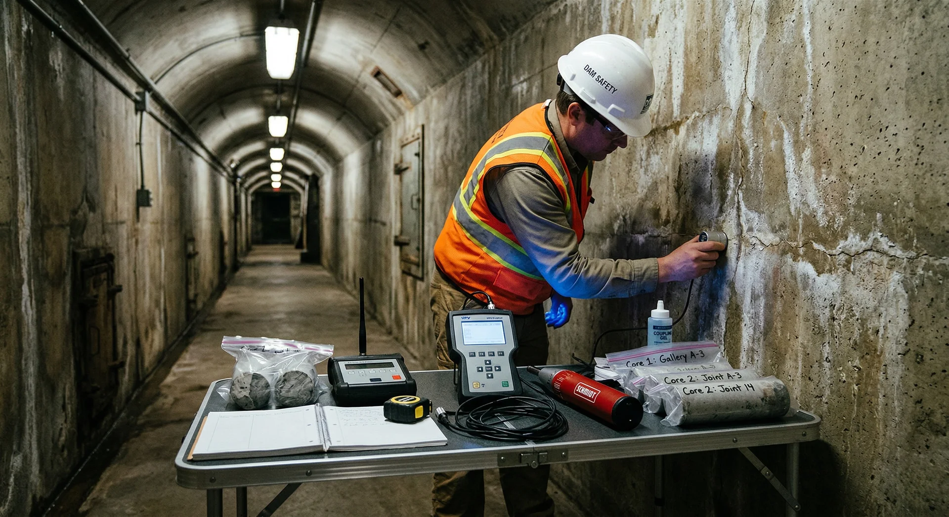
2. Ultrasonic Pulse Velocity (UPV)
What it does: Measures the speed of an ultrasonic pulse transmitted through concrete. Higher velocity indicates denser, stronger concrete. Lower velocity indicates voids, cracks, or deterioration.
Indian Standard: IS 13311 Part 1:1992
How it works on a dam: A transmitting transducer sends an ultrasonic pulse into the concrete from one surface. A receiving transducer on the opposite surface (direct transmission) or the same surface (indirect transmission) detects the pulse. The travel time over the known path length gives the pulse velocity.
Velocity classification (per IS 13311):
| Pulse Velocity (km/s) | Concrete Quality |
|---|---|
| Above 4.5 | Excellent |
| 3.5 to 4.5 | Good |
| 3.0 to 3.5 | Medium |
| Below 3.0 | Doubtful |
What it reveals:
- Internal concrete quality throughout the full cross-section (not just the surface)
- Location and approximate extent of internal cracks and voids
- Depth of fire or weathering damage
- Uniformity of concrete across the structure
- Combined with rebound hammer (SonReb method), provides more reliable strength estimates than either test alone
Limitations:
- Requires access to opposite faces for direct transmission (the most accurate mode). On thick dam sections, this may require gallery access.
- Affected by moisture content, reinforcement (steel conducts ultrasound faster than concrete), and aggregate type.
- Cannot identify the specific cause of deterioration, only its presence and extent.
When to use it: As the primary volumetric assessment tool. Where rebound hammer tells you about the surface, UPV tells you about the interior. Essential for any dam concrete assessment.
3. Impact Echo
What it does: Sends a stress wave into concrete by mechanical impact (a small steel sphere) and analyses the frequency of the reflected wave. The reflection pattern reveals the concrete thickness, internal voids, delaminations, and other discontinuities.
How it works on a dam: A small impactor strikes the concrete surface, generating a stress wave that travels through the concrete and reflects off the back surface, internal defects, or changes in material. An adjacent receiver captures the reflected waves. Frequency analysis of the reflected signal reveals the depth and nature of reflecting surfaces.
What it reveals:
- Concrete thickness (critical for verifying as-built dimensions against design)
- Internal delaminations and debonding (common in older dams with deteriorated lift joints)
- Voids and honeycombing within the concrete mass
- Depth of surface-parallel cracks
- Condition of grouted ducts and post-tensioning systems
Limitations:
- Requires a relatively smooth testing surface
- Interpretation requires specialist expertise. The frequency spectra can be complex, and misinterpretation is possible.
- Depth of investigation limited to approximately 1-2 metres depending on concrete quality and impactor size
When to use it: When UPV has identified zones of concern and you need to characterize the specific defect (delamination vs. void vs. crack). Particularly valuable for assessing lift joint condition in gravity dams and identifying delamination in spillway slabs.
4. Ground Penetrating Radar (GPR)
What it does: Transmits electromagnetic pulses into concrete and records reflections from internal interfaces: voids, reinforcement, embedded objects, changes in material, moisture boundaries, and deterioration zones.
How it works on a dam: A GPR antenna is moved across the concrete surface, either on a survey wheel or by hand. The antenna transmits electromagnetic pulses and records the reflected signals as a continuous profile. The resulting image (radargram) shows subsurface features as a cross-section.
What it reveals:
- Location and depth of reinforcement (rebar mapping)
- Voids beneath concrete slabs (critical for spillway assessments where undermining is a concern)
- Internal moisture distribution (indicating seepage paths)
- Embedded objects and conduits
- Concrete layer interfaces and as-built thickness variation
Limitations:
- Penetration depth depends on concrete conductivity. Wet, chloride-contaminated, or heavily reinforced concrete reduces penetration significantly.
- Cannot penetrate through steel reinforcement mats (the radar signal reflects off the first layer)
- Requires specialist equipment and experienced interpretation
- Results are qualitative images, not direct strength measurements
When to use it: For mapping subsurface features across large areas. GPR excels at identifying voids beneath spillway slabs (a safety-critical defect), mapping reinforcement in structures where drawings are unavailable, and locating seepage paths through dam sections. It is the fastest method for surveying large concrete surfaces.
5. Core Extraction and Laboratory Testing
What it does: Extracts a cylindrical concrete sample (core) from the structure using a diamond-tipped rotary drill. The core is then tested in a laboratory for compressive strength, elastic modulus, and petrographic examination.
Indian Standards: IS 516 Part 1 (compressive strength testing), IS 2386 Part 8 (petrographic examination)
How it works on a dam: Diamond core drilling equipment is set up at predetermined locations identified by NDT screening. Cores are typically 75 mm or 100 mm in diameter and must be long enough to include the feature of interest (lift joint, deterioration zone, full section). Cores are carefully extracted, labelled, photographed, and transported to a laboratory.
What it reveals:
- Actual compressive strength (the definitive measurement, unlike NDT estimates)
- Elastic modulus and Poisson’s ratio (for structural analysis inputs)
- Petrographic composition: aggregate type, cement paste condition, void structure, and evidence of deterioration mechanisms (AAR gel, ettringite, carbonation depth)
- Chloride content profile (for corrosion risk assessment)
- Water absorption and porosity
Limitations:
- Destructive: creates a hole in the structure that must be repaired
- Slow and expensive compared to NDT methods
- Limited number of locations can be tested (typically 10-50 cores for a major dam assessment, compared to hundreds of NDT test points)
- Results reflect only the specific location cored. Concrete quality can vary significantly across a dam.
- Core extraction in operating dams requires careful planning to avoid galleries, drainage systems, and structural elements
When to use it: After NDT screening has identified areas of concern and the assessment team needs definitive data on concrete strength and condition. Core extraction is essential for diagnosing AAR (petrographic examination is the only conclusive test), determining actual strength for structural analysis, and providing calibration data for NDT interpretation.
The Assessment Workflow
These five methods work as a system, not as standalone tests. The recommended workflow for a dam concrete assessment:
Step 1: Visual Survey Systematic documentation of all visible deterioration: cracking, spalling, efflorescence, seepage staining, joint condition, drain output, and surface erosion. Photographs and mapping.
Step 2: Rebound Hammer Screening Rapid screening of accessible surfaces to identify areas with anomalous surface hardness. Grid-based testing across dam face, galleries, spillway, and appurtenant structures.
Step 3: UPV Investigation Volumetric assessment of zones identified in Step 2, plus systematic coverage of critical structural elements. Direct transmission where opposite faces are accessible (galleries, piers), indirect transmission elsewhere.
Step 4: Impact Echo / GPR (as needed) Targeted investigation of specific concerns: suspected delaminations (impact echo), suspected voids beneath slabs (GPR), reinforcement mapping (GPR), thickness verification (impact echo).
Step 5: Core Extraction (targeted) Definitive testing at locations identified in Steps 2-4. Cores taken from representative good concrete, deteriorated zones, and lift joints. Laboratory testing for strength, elastic properties, and petrographic examination.
Step 6: Integrated Assessment All data combined into a comprehensive condition report: concrete quality map, deterioration mechanism identification, structural adequacy assessment, and recommendations for monitoring, maintenance, or rehabilitation.
What Dam Owners Should Do Now
With the Dam Safety Act’s December 2026 deadline for comprehensive evaluation approaching:
-
Identify your assessment needs. How many concrete structures require evaluation? What is their age, condition, and access situation?
-
Budget for NDT. A comprehensive NDT programme for a major dam typically costs a fraction of 1% of the dam’s replacement value. Compare this to the cost of structural failure or regulatory non-compliance.
-
Engage specialists early. NDT equipment is widely available. NDT interpretation for dam concrete requires specialist experience. The difference between a useful assessment and a stack of meaningless numbers is the engineer reading the data.
-
Plan for follow-up. NDT identifies problems. Rehabilitation solves them. Budget and timeline should account for the full cycle: assessment, diagnosis, design, and repair.
-
Document everything. The Act requires that evaluation results be reported to the SDSO. Comprehensive documentation protects dam owners legally and provides the baseline for future monitoring.
The concrete in your dam has been performing for decades. The question is whether it will continue to perform for decades more. NDT provides the answer, if you ask the right questions.