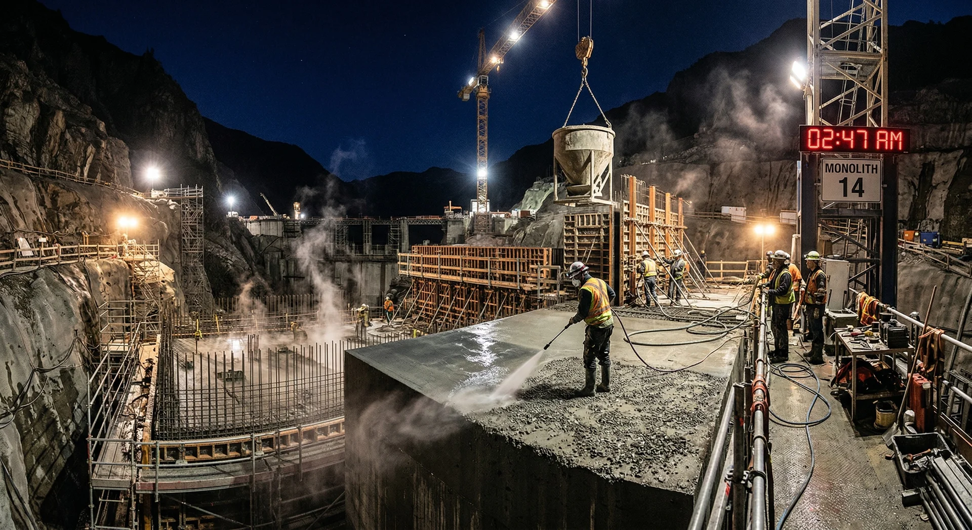
The true cost of concrete quality failures
Concrete quality problems are not merely technical inconveniences. They are project-critical events that cascade through schedules, budgets, and structural integrity. Research on large dam projects worldwide shows an average schedule overrun of 44%, with 88% of delayed projects also experiencing cost overruns. While concrete quality is not the sole cause, it is the most controllable one.
Every concrete quality failure triggers the same sequence: detection → investigation → root cause analysis → repair design → repair execution → verification → documentation. This sequence takes days to weeks for minor issues and months for major failures. During this time, downstream construction activities that depend on the affected concrete are halted.
What is a concrete quality failure?
A concrete quality failure is any deviation from the project's concrete specification that requires investigation, corrective action, or repair. This includes test results below specified strength, visible defects (cracking, honeycombing, segregation), temperature exceedances, and material non-conformances. Every failure has a root cause, and every root cause has a preventive measure.
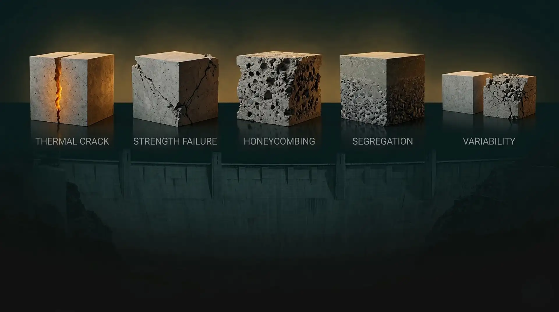
The five problems documented below represent the most frequent quality failures observed on hydroelectric projects across India, Bhutan, and Nepal, drawn from PCCI’s 40+ years of field experience.
Problem 1: Thermal cracking
Thermal cracking is the most consequential concrete defect on dam projects. It occurs when the temperature differential between the hot interior and cooler surface of a mass concrete placement exceeds the concrete’s tensile strain capacity, typically at a differential of 19-20°C.
Why it happens:
- High cement content generating excessive heat of hydration
- Inadequate pre-cooling of concrete ingredients
- Missing or undersized post-cooling systems
- Insufficient surface insulation during curing
- Rapid ambient temperature drops (cold fronts, nighttime cooling at altitude)
- Lift heights exceeding the thermal capacity of the cooling system
The impact: A single thermal crack in a dam creates a permanent seepage path. The structural assessment alone, including coring, permeability testing, and structural analysis, takes 1-3 weeks. Repair (grouting, crack injection) adds another 1-2 weeks. If the crack is structurally significant, the entire placement strategy may need revision.
How to prevent it:
| Prevention Strategy | Implementation | Impact |
|---|---|---|
| Low-heat cementitious system | Fly ash 25-50% or GGBS 50-70% replacement | Reduces heat by 30-50% |
| Pre-cooling | Chilled water, ice, aggregate cooling | Lowers placement temp to 10-15°C |
| Post-cooling | Embedded cooling pipes, circulated water | Extracts heat during curing |
| Surface insulation | Insulating blankets, curing compounds | Prevents surface temperature shock |
| Thermal monitoring | Embedded thermocouples, real-time data | Early warning before cracking |
PCCI’s Thermal Control & Placement Engineering service addresses each of these prevention strategies as an integrated programme, from pre-construction thermal modelling through construction-phase monitoring and adjustment.
Key Takeaway
Thermal cracking is the single most expensive concrete defect to repair on a dam project, and the single most preventable through proper planning. A comprehensive thermal control programme costs 2-5% of the concrete works budget. Repairing thermal cracks costs 15-30%.
Problem 2: Compressive strength shortfalls
Compressive strength shortfalls occur when concrete test specimens fail to meet the specified minimum strength at the compliance testing age (typically 28, 56, or 90 days). This triggers formal non-conformance procedures, which can escalate to demolition and reconstruction in severe cases.
Why it happens:
- Aggregate source variability (changes in gradation, moisture, or mineralogy)
- Cement or SCM quality variation between supply batches
- Batching errors (incorrect proportions, miscalibrated equipment)
- Excess water at the point of placement (rain, additional water for workability)
- Inadequate curing (premature form removal, insufficient moisture)
- Testing errors (improper specimen preparation, non-standard curing, machine calibration)
The impact: Three consecutive failed tests typically trigger a formal non-conformance report (NCR). The investigation requires core sampling from the in-situ structure, additional testing, and structural reassessment. If the strength shortfall is confirmed in the structure (not just in test specimens), the options are remedial measures, load restriction, or in worst cases, demolition.
How to prevent it:
- Pre-qualification testing: Comprehensive testing of all cement, SCM, aggregate, and admixture sources before construction, following ASTM and IS/BIS testing protocols. Identify variability ranges and adjust mix designs accordingly.
- Statistical process control: Control charts tracking every batch’s strength results. Identify downward trends 2-3 weeks before failures occur, allowing proactive adjustment.
- Batch plant calibration: Regular calibration of scales, moisture probes, and dispensing systems. Automated batching with tolerances set tighter than specification requirements.
- Water management: Strict control of water-to-cementitious ratio at the point of placement. Rain protection for fresh concrete. No site-added water without proportioning adjustment.
PCCI’s QA/QC Systems service establishes statistical process control from the first batch, enabling predictive quality management rather than reactive failure response.
Problem 3: Honeycombing
Honeycombing is a surface defect characterised by voids where coarse aggregate is visible without surrounding mortar. It indicates incomplete consolidation: the vibration effort was insufficient to remove entrapped air and fully compact the concrete around the aggregate.
Why it happens:
- Insufficient vibration (too few vibrators, inadequate insertion depth, incorrect spacing)
- Concrete placed too stiffly (low slump, high coarse aggregate content)
- Complex formwork geometry restricting vibrator access
- Excessive free-fall height causing aggregate-mortar separation before the concrete reaches the formwork
- Placement rate exceeding the consolidation capacity of the vibration equipment
- Poorly trained placement crews
The impact: Surface honeycombing reduces cover depth (exposing reinforcement to corrosion), creates water ingress paths, and reduces the effective cross-section for load transfer. In hydraulic structures (dams, tunnels, intake structures), any surface defect is a potential seepage path.
How to prevent it:
- Design mixes with adequate workability for the placement conditions
- Specify and enforce vibration protocols (vibrator type, insertion depth, spacing, duration)
- Limit free-fall height to 1.5 metres maximum (per ACI 304R)
- Use tremie pipes or drop chutes for deep placements
- Ensure adequate vibrator coverage (one vibrator per 0.5 m² of placement face)
- Train and certify placement crews before they work on critical pours
What is the difference between honeycombing and rock pockets?
Honeycombing is surface-level incomplete consolidation where mortar is missing between visible coarse aggregates. Rock pockets are deeper voids: cavities where concrete failed to fill a section of formwork entirely. Rock pockets are structurally more serious and typically indicate a more fundamental placement or mix design problem.
Problem 4: Segregation
Segregation is the separation of concrete’s constituent materials: coarse aggregate sinking while mortar rises, or bleed water accumulating at the surface. It produces zones of weak, porous concrete within a nominally uniform placement.
Why it happens:
- Excessive free-fall height (drops exceeding 1.5 metres cause differential settling)
- Over-vibration (excessive vibration duration causes heavy aggregate to migrate downward)
- Inadequate mix cohesion (incorrect sand-to-aggregate ratio, insufficient fines)
- Excessive water content (over-wet mixes are inherently unstable)
- Pumping at excessive pressure or through lines with inadequate diameter
- Discharging into formwork at too high a rate for the placement geometry
The impact: Segregated zones have variable strength, permeability, and durability within the same pour. The top surface may have excess mortar (weak, crack-prone), while the bottom has excess coarse aggregate (porous, poor bond). In a dam, this creates horizontal planes of weakness, exactly where you need monolithic integrity.
How to prevent it:
- Mix design: Ensure adequate fine aggregate content and cohesive paste volume. Use air-entraining and water-reducing admixtures as needed.
- Placement control: Limit drop heights, use tremie pipes, place in controlled lift thicknesses.
- Vibration discipline: Define maximum vibration duration per insertion point. Over-vibration is as harmful as under-vibration.
- Pump line management: Proper pump line diameter, gradual curves, priming with grout before concrete.
Key Takeaway
Segregation is a mix design problem and a placement discipline problem. If the mix is properly designed for the placement conditions, with adequate cohesion, correct slump, and appropriate aggregate proportions, and placement crews follow controlled procedures, segregation does not occur. It is one of the most preventable defects.
Problem 5: Batch-to-batch variability
Batch-to-batch variability is the inconsistency in concrete properties (strength, workability, air content) between successive batches produced from the same mix design. High variability means that even if the average strength meets specification, individual batches may fall below, triggering failures and non-conformances.
Why it happens:
- Aggregate moisture variation: Natural aggregates absorb water variably. If the batching system does not adjust water content for aggregate moisture, the effective water-to-cementitious ratio varies from batch to batch.
- Aggregate gradation drift: Quarry production gradually changes the gradation of aggregates over time. What was a well-graded source in month 1 may be gap-graded by month 6.
- Cement and SCM supply changes: Different production lots of cement or fly ash may have measurably different properties: fineness, chemical composition, reactivity.
- Batching equipment drift: Scales lose calibration, moisture probes drift, admixture pumps wear. Without regular verification, systematic errors accumulate.
- Environmental conditions: Ambient temperature affects concrete temperature, setting time, and early strength development. What works at 15°C may not perform at 40°C.
The impact: High variability forces the mix designer to “over-design,” specifying higher cement content than structurally necessary to ensure that even the weakest batches still pass specification. This waste increases cost, heat, and carbon emissions. More importantly, it masks the underlying process control problems that eventually produce serious failures.
How to prevent it:
- Aggregate moisture monitoring: Real-time moisture probes in aggregate bins with automatic batching adjustment
- Regular source testing: Weekly aggregate gradation and absorption testing to detect drift before it affects concrete
- Statistical process control: Control charts tracking not just individual results but trends, variability (standard deviation), and the coefficient of variation
- Cement and SCM fingerprinting: Testing each delivery lot and adjusting mix proportions as needed
- Batch plant audits: Monthly calibration verification of all batching equipment
- Seasonal mix adjustments: Modified proportions for hot weather and cold weather concreting
PCCI’s QA/QC Systems + Lab & Testing Programs service builds a comprehensive quality management system that addresses variability at its source, not just testing the output but controlling the inputs.
The QC system that prevents all five
These five problems are not independent. They share common root causes: insufficient material testing, inadequate process control, untrained crews, and absent independent oversight.
A comprehensive concrete quality programme addresses them systematically:
- Pre-construction: Material investigation, trial mixes, QC manual preparation, crew training
- Production: Batch plant monitoring, statistical process control, real-time adjustments
- Placement: Temperature monitoring, vibration supervision, lift management, surface protection
- Post-placement: Curing management, thermal monitoring, strength trend analysis, NCR management
- Independent review: Third-party quality oversight ensuring contractor compliance
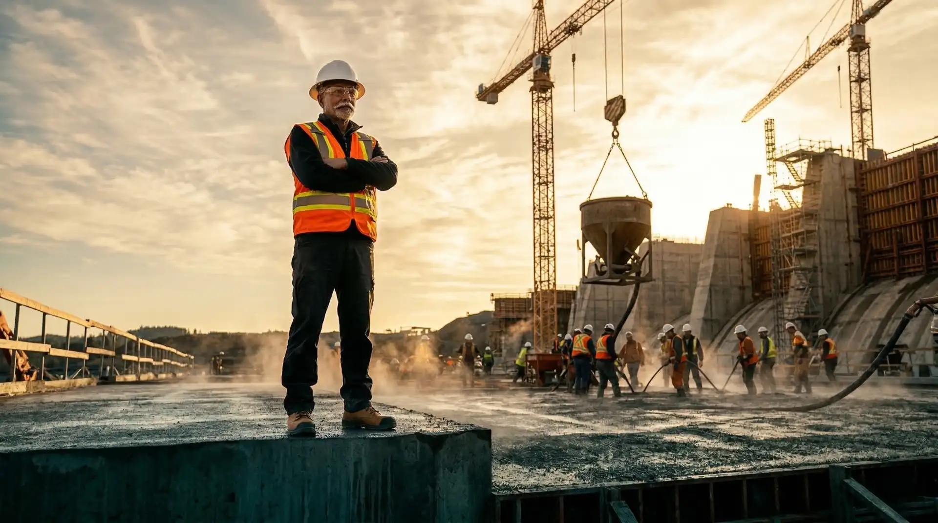
PCCI's approach
With deep field experience across landmark hydroelectric projects totalling 4,000+ MW, PCCI's leadership has seen, and resolved, every one of these problems. Our Construction Troubleshooting & Root Cause Analysis service provides rapid response when problems emerge. Our QA/QC Systems service prevents them from occurring in the first place. Prevention is always cheaper, faster, and more reliable than repair.
Book a Technical Call → to discuss quality management for your concrete programme.