Water is the load that a dam resists, and water is the force that seeks to penetrate every joint, crack, and pore in the dam body. A concrete dam is not a single cast element. It is an assembly of hundreds of individually placed concrete lifts arranged in monolith blocks separated by contraction joints. Every boundary between these elements is a potential pathway for water.
The waterproofing system, comprising waterstops at joints, sealants on surfaces, drainage between barriers, and treatment of galleries, is the engineered defence that controls this water movement. The system does not aim to make the dam completely impervious. That is neither possible nor desirable: controlled seepage through drains is part of the design, reducing uplift pressure and providing monitoring data. The system aims to control where water flows, how much flows, and to prevent water from reaching locations where it would cause structural damage or undermine stability.
Joint Types in Concrete Dams
Understanding the waterproofing requirements begins with understanding the joints.
Contraction Joints (Monolith Joints)
Contraction joints are the vertical joints between adjacent monolith blocks. They serve a critical thermal function: allowing each monolith to contract independently as the concrete cools from its peak hydration temperature to its final stable temperature.
Spacing. Contraction joints are typically spaced at 15 to 20 metres in gravity dams and 8 to 15 metres in arch dams. Wider spacing increases the thermal contraction per joint (and the required joint movement capacity) but reduces the total number of joints and the associated waterproofing effort.
Movement. The expected opening of a contraction joint depends on the monolith width, the temperature drop, and the coefficient of thermal expansion of the concrete. For a 20-metre monolith with a 25-degree Celsius temperature drop and a thermal coefficient of 10 x 10⁻⁶ per degree Celsius, the contraction is:
20 m x 25°C x 10 x 10⁻⁶ = 5 mm
This 5 mm of movement must be accommodated by the waterstop and sealant without compromising the seal. In arch dams where contraction joints may be later grouted to achieve monolithic action, the joints must first open fully (requiring the concrete to cool to its final temperature) before grouting.
Construction Joints (Lift Joints)
Construction joints are horizontal joints between successive concrete lifts within a monolith. They form where one day’s placement ends and the next begins.
Treatment requirements. Construction joints must be prepared to achieve bond between the old and new concrete. Per IS 457:1957 and established dam construction practice, preparation involves:
- Remove laitance and weak surface mortar by green cutting (water jetting while the concrete is still green, 6 to 12 hours after placement) or by mechanical scabbling after hardening
- Clean the joint surface with air-water jet to remove all loose material
- Saturate the surface with water, then allow to reach saturated surface-dry condition before placing the next lift
- Apply a layer of bedding mortar (cement-sand mortar, 10 to 15 mm thick) immediately before placing the new concrete
Construction joints in the lower portion of the dam, where hydrostatic pressures are highest, may include waterstops. In the upper portion, where pressures are lower, proper surface preparation and bonding is typically sufficient.
Expansion Joints
Expansion joints are less common in concrete dams than in building construction because the dam is in a relatively stable thermal environment after construction. However, expansion joints may be used at transitions between the dam and appurtenant structures (spillway walls, powerhouse walls, intake structures) where differential movement is expected.
Expansion joints incorporate compressible filler material (typically closed-cell polyethylene foam or bituminous filler) to accommodate the expected movement, with waterstops and sealants providing the waterproofing function.
Waterstop Systems
PVC Waterstops
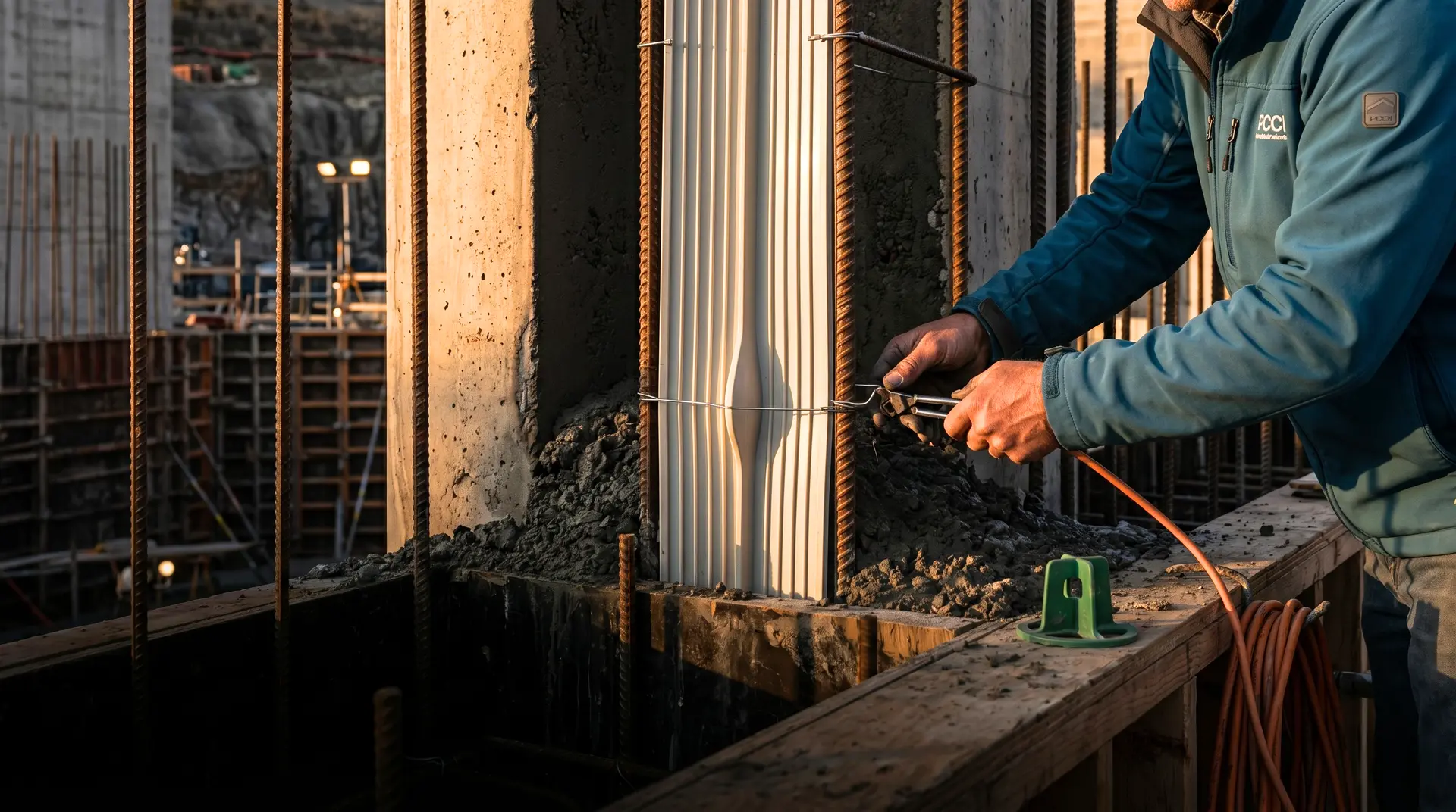
PVC waterstops are the standard waterproofing element for joints in concrete dams. They are embedded in the concrete on both sides of the joint, with a central section that spans the joint and deforms to accommodate movement.
Profile types:
| Profile | Application | Movement Capacity |
|---|---|---|
| Dumbbell (centre bulb) | Contraction joints with movement | High (accommodates opening and closing) |
| Ribbed flat | Construction joints with minimal movement | Low (shear resistance, not movement) |
| Serrated | Expansion joints | Moderate (compresses and extends) |
| External (surface-mounted) | Retrofit waterproofing | Varies by design |
Material specification for dam applications:
| Property | Requirement | Test Standard |
|---|---|---|
| Shore A hardness | 70-80 | ASTM D2240 |
| Tensile strength | Greater than 12 MPa | ASTM D412 |
| Elongation at break | Greater than 300% | ASTM D412 |
| Tear resistance | Greater than 25 kN/m | ASTM D624 |
| Water absorption (7 days) | Less than 0.3% | ASTM D471 |
| Low temperature brittleness | Pass at -35°C | ASTM D746 |
| Compression set | Less than 25% | ASTM D395 |
Width selection. The waterstop width determines its embedment depth in the concrete on each side of the joint. Standard practice for dams:
| Hydrostatic Head | Minimum Waterstop Width |
|---|---|
| Less than 15 m | 150 mm |
| 15-30 m | 200 mm |
| 30-60 m | 230 mm |
| Greater than 60 m | 300 mm |
Per IS 12200:2001, which covers PVC waterstops for concrete joints, the minimum embedment on each side of the joint should be at least one-third of the total waterstop width.
Copper Waterstops
For high-head dams, critical joints, or where long-term reliability without maintenance is essential, copper waterstops provide the highest performance.
Material. Soft copper sheet, 1.5 to 2.0 mm thick, IS 191 Grade ETP or equivalent. The copper must be in the fully annealed condition to ensure ductility.
Fabrication. Copper waterstops are formed into a corrugated or bent profile that accommodates joint movement. The corrugation acts as an expansion loop, allowing the waterstop to stretch as the joint opens without tearing. Joints between copper sheets are made by welding (oxy-acetylene or TIG welding) or brazing, producing a watertight connection.
Advantages over PVC:
- Indefinite service life in embedded conditions (copper does not degrade)
- Higher pressure resistance
- No possibility of material embrittlement over time
- Can be welded in the field to produce watertight connections at intersections and corners
Disadvantages:
- 5 to 10 times more expensive than PVC
- Requires skilled welders for field joints
- More difficult to install (rigid compared to flexible PVC)
- Can be damaged by vibrators during concrete placement
Hydrophilic Waterstops
Hydrophilic waterstops are strips of bentonite-rubber compound that swell on contact with water, forming a compression seal between the waterstop and the concrete. They are installed on the surface of one concrete element before the adjacent element is placed.
Applications in dams:
- Secondary seal behind primary PVC or copper waterstops
- Construction joints in low-pressure zones
- Retrofit waterproofing where embedded waterstops were omitted
- Pipe and conduit penetrations through dam concrete
Limitations:
- Not suitable as the sole waterstop in high-head joints
- Swelling is reduced in highly alkaline environments (pH greater than 12)
- Can be washed away if water is flowing across the surface during installation
- Limited movement capacity (typically less than 5 mm)
Joint Sealant Systems
Surface Sealants
Joint sealants are applied in a formed groove on the upstream face of the dam at each contraction joint. They provide the first line of defence against water entry and are the only component that can be inspected and replaced during the dam’s operating life.
Sealant types for dam applications:
| Sealant Type | Movement Capacity | Adhesion | Life Expectancy | Cost |
|---|---|---|---|---|
| Polysulphide | Plus or minus 25% | Good on clean concrete | 15-25 years | Moderate |
| Polyurethane | Plus or minus 25% | Excellent | 15-20 years | Moderate |
| Silicone | Plus or minus 50% | Fair (requires primer) | 20-30 years | Higher |
| Epoxy-polysulphide | Plus or minus 15% | Excellent | 20-30 years | Higher |
Groove design. The sealant groove is formed in the concrete at the upstream face of each contraction joint. The groove dimensions determine the sealant performance:
- Width. Based on the expected joint movement. The sealant must not be stretched beyond its movement capacity. Minimum groove width is typically 20 mm.
- Depth. The sealant depth should be approximately half the width. A depth-to-width ratio of 0.5 produces a sealant cross-section that deforms uniformly when the joint opens or closes.
- Shape factor. The ratio of depth to width. A shape factor of 0.5 to 1.0 is optimal. Shape factors exceeding 1.0 create high stress concentration at the sealant-concrete bond line, leading to adhesive failure.
- Bond breaker. A bond-breaking tape (polyethylene or foam) is placed at the bottom of the groove to prevent the sealant from adhering to the bottom surface. This ensures that the sealant stretches in two dimensions (width) rather than three (width plus depth), reducing the stress on the adhesive bond.
Joint Groove Preparation
The performance of any sealant depends on the quality of the substrate preparation:
- Clean the groove surfaces with high-pressure water jet (minimum 10 MPa) to remove laitance, efflorescence, and loose material
- Dry the groove if the sealant requires a dry substrate (check manufacturer’s requirements; some polyurethane sealants tolerate damp surfaces)
- Apply primer if required by the sealant manufacturer
- Install the bond-breaker tape
- Apply the sealant using a pressure gun, filling from the bottom up to avoid air entrapment
- Tool the sealant surface to achieve a concave profile that is recessed below the concrete face
Multi-Line Defence System
The waterproofing system at a contraction joint in a concrete dam is a layered defence, not a single barrier. The standard arrangement, from upstream to downstream:
Line 1: Surface sealant. The first barrier, accessible for inspection and replacement. Prevents direct water entry into the joint from the reservoir face.
Line 2: Primary waterstop. Embedded in the concrete, 150 to 300 mm from the upstream face. PVC (dumbbell profile) or copper. This is the main waterproofing element.
Line 3: Drainage zone. A formed groove or porous drain strip between the primary and secondary waterstops. Any water that passes the primary seal is collected here and directed to the dam’s internal drainage system (gallery drains). This drainage zone is critical: it prevents pressure buildup between the waterstop lines.
Line 4: Secondary waterstop. A backup seal downstream of the drainage zone. Typically PVC (can be a simpler profile than the primary). It prevents water from bypassing the drainage zone and entering the dam body downstream of the drains.
This four-line system means that any single component can fail without resulting in uncontrolled seepage through the dam. The surface sealant can deteriorate (it is exposed to UV and weathering); the drainage zone catches what passes it. The primary waterstop can develop a local defect; the drainage zone and secondary waterstop provide backup.
The system design follows principles established by ICOLD and documented in multiple technical bulletins on dam waterproofing and joint treatment.
Gallery Waterproofing
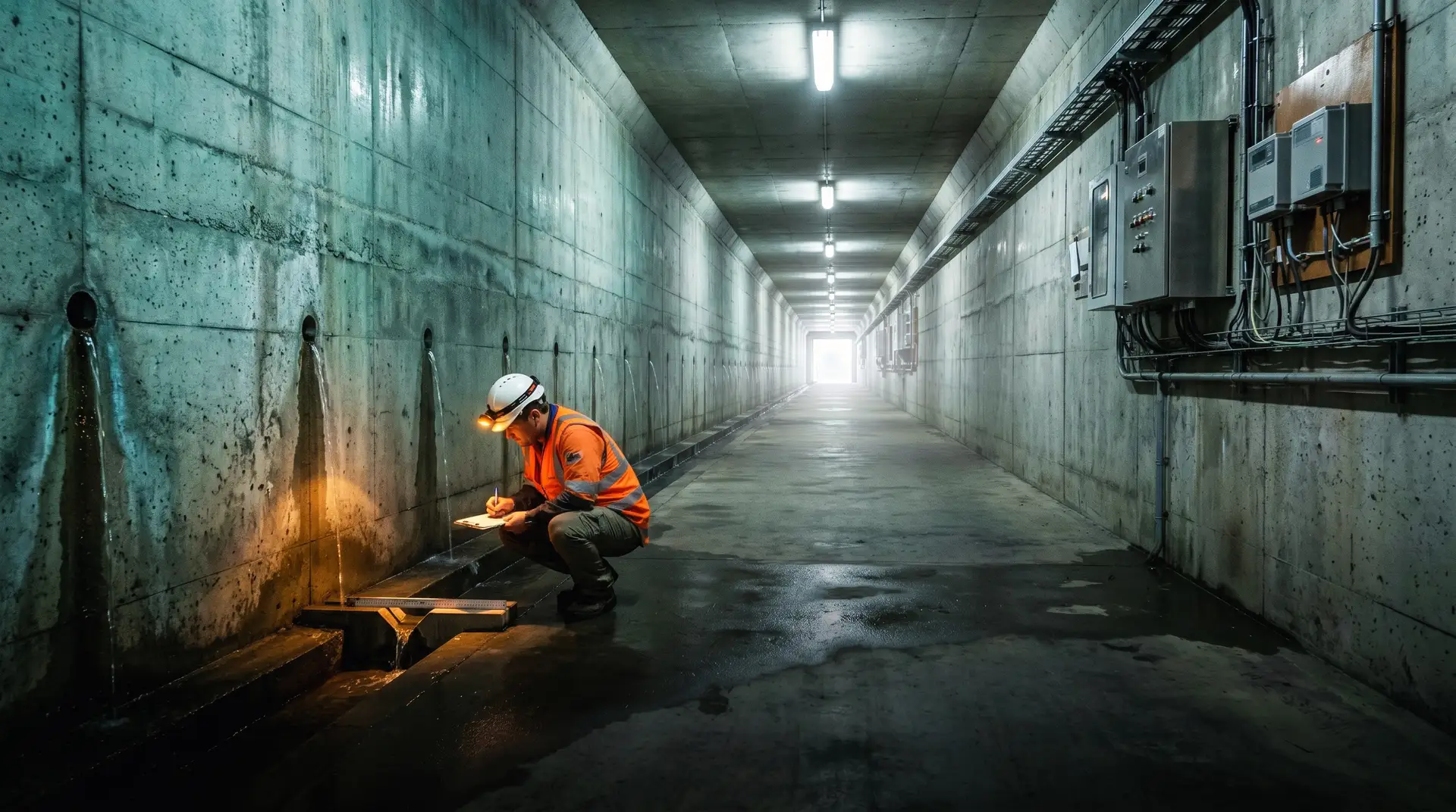
Dam galleries (inspection tunnels within the dam body) are surrounded by concrete under hydrostatic pressure. Water migrates through the concrete and emerges on the gallery walls, ceiling, and floor as seepage. Some seepage is expected and designed for; excessive seepage indicates either poor concrete quality, deteriorated joints, or deficient waterproofing.
Gallery Drainage System
The primary method of managing gallery water is drainage rather than waterproofing. The gallery floor is sloped toward collection points (sumps), and drain pipes embedded in the dam connect foundation drains to the gallery. Water collected in the gallery is measured (as a dam safety monitoring parameter) and pumped or gravity-drained to the downstream area.
Gallery Surface Treatment
Where gallery seepage is excessive or where dry conditions are needed for electrical equipment or instrumentation, surface treatments can reduce water ingress:
Crystalline waterproofing. Applied as a slurry coat on damp concrete surfaces, crystalline waterproofing reacts with moisture and free lime in the concrete to form insoluble crystals within the concrete pore structure. These crystals block the water migration pathways. The treatment becomes part of the concrete and reactivates if new cracks form.
Injection grouting. Active leaks through cracks or joints are sealed by injecting polyurethane or epoxy resin into the crack from the gallery side, drawing on the same techniques used for foundation contact grouting. The injected material fills the crack and stops the water flow.
Drainage membranes. Sheet membranes with a dimpled profile are installed on the gallery walls, creating an air gap that allows water to flow down behind the membrane to a collection channel at the floor level. The membrane does not stop the water; it manages it by directing it to the drainage system.
Pipe and Conduit Penetrations
Every pipe, conduit, and cable that penetrates the dam concrete creates a potential leakage path. Penetrations must be sealed with:
- A puddle flange (steel plate welded to the pipe, embedded in the concrete to block flow along the pipe exterior)
- Waterstop collars around the pipe at each concrete joint
- Non-shrink grout packing in the annular space between the pipe and the concrete
- Hydrophilic sealing strips on the pipe surface within the concrete
The detailing of penetrations is frequently a source of leakage problems on dams. Each penetration must be designed and inspected individually, particularly at junctions between the pipe, the waterstop system, and the concrete.
Installation Quality Control
Waterstop and sealant performance depends critically on installation quality. Material specifications alone do not ensure waterproofing performance; installation practices must be specified and verified through a structured QA/QC programme.
Waterstop Installation Checks
| Check | Requirement | When |
|---|---|---|
| Material certification | Test certificates for all waterstop material delivered to site | Before installation |
| Alignment | Waterstop centred on joint, held in position by split formwork or support chairs | Before concrete placement |
| Continuity | All waterstop joints (splices, tees, crosses) made by thermal welding per manufacturer’s procedure | Before concrete placement |
| Concrete placement | Vibrators kept minimum 150 mm from waterstop to prevent displacement | During placement |
| Vibration | Concrete fully compacted around waterstop, no honeycombing or voids | During placement |
| Post-pour verification | Visual inspection of waterstop position on form removal | After form stripping |
Common Installation Defects
- Waterstop displacement. Vibrators pushed against the waterstop during concrete compaction, displacing it from the joint centre line. The waterstop no longer spans the joint symmetrically, reducing its movement capacity and sealing effectiveness.
- Honeycomb around waterstop. Inadequate vibration near the waterstop (to avoid displacement) leaves voids in the concrete adjacent to the seal. Water can bypass the waterstop through these voids.
- Splice failure. Field splices that are not properly welded (insufficient heat, contaminated surfaces, or incorrect technique) create gaps in the waterstop continuity.
- Tear or puncture. Reinforcement bars, form ties, or sharp objects can tear the PVC during or before concrete placement. Any damage must be identified and repaired before the damaged section is covered with concrete.
Maintenance and Rehabilitation
Routine Inspection
Joint waterproofing systems should be inspected annually as part of the broader dam concrete deterioration monitoring programme. The inspection covers:
- Condition of surface sealants (cracking, debonding, extrusion, loss of elasticity)
- Seepage at joints visible from the gallery or downstream face
- Condition of drainage systems (blocked drains, standing water in drainage channels)
- Movement monitoring at contraction joints (to verify that waterstops are within their capacity)
Sealant Replacement
Surface sealants have finite service lives and must be replaced periodically. The replacement procedure involves:
- Remove the old sealant completely (mechanical cutting or pulling)
- Clean and inspect the groove for concrete deterioration
- Repair any concrete damage in the groove
- Re-prime the groove surfaces
- Install new bond-breaker tape
- Apply new sealant to the full groove depth
- Tool and cure
Sealant replacement is a routine maintenance item that is planned for during the dam’s operating life. A well-designed groove with adequate access (above the reservoir level or in the dam gallery) makes replacement straightforward. Grooves that are submerged require dewatering or specialist divers for replacement.
Waterstop Rehabilitation
When an embedded waterstop fails and cannot be accessed for direct repair, the troubleshooting and root-cause analysis process determines the most practical of the following alternative approaches:
- Injection grouting. Injecting polyurethane or epoxy into the joint from the gallery or upstream face to create a new seal at or near the waterstop location.
- External waterstop installation. Bonding a surface-mounted waterstop (rubber or PVC) to the upstream face over the joint. This requires draining the reservoir or working underwater.
- Internal drainage enhancement. If the waterstop cannot be repaired, improving the drainage system downstream of the failed waterstop to manage the increased seepage may be the most practical solution.
Waterstop rehabilitation is expensive and disruptive. Prevention through proper installation is far more cost-effective than any repair.
Conclusion
The waterproofing and joint treatment system of a concrete dam is a multi-component, multi-line defence that must function for the full service life of the structure, typically 100 years or more. No single element of the system can be relied upon exclusively. The surface sealant, the primary waterstop, the drainage zone, and the secondary waterstop each have a role, and the system is designed so that the failure of any one element is contained by the others.
The materials are well understood. PVC and copper waterstops have proven track records spanning decades. Polysulphide and polyurethane sealants are mature products with predictable performance. Crystalline waterproofing and injection grouting provide effective treatments for in-service problems.
The vulnerability lies not in the materials but in the installation. A waterstop displaced during concrete placement, a splice inadequately welded, a sealant applied to an unprepared surface: these installation defects, invisible once the concrete is placed, become the leakage pathways that require expensive rehabilitation decades later. Quality control during installation, verified by inspection at every step, is the investment that determines whether the waterproofing system performs as designed or becomes a source of chronic problems for the dam’s operating life. It is the foundation of durability and service-life design for a structure that must perform for a century.