The weakest plane in the strongest structure
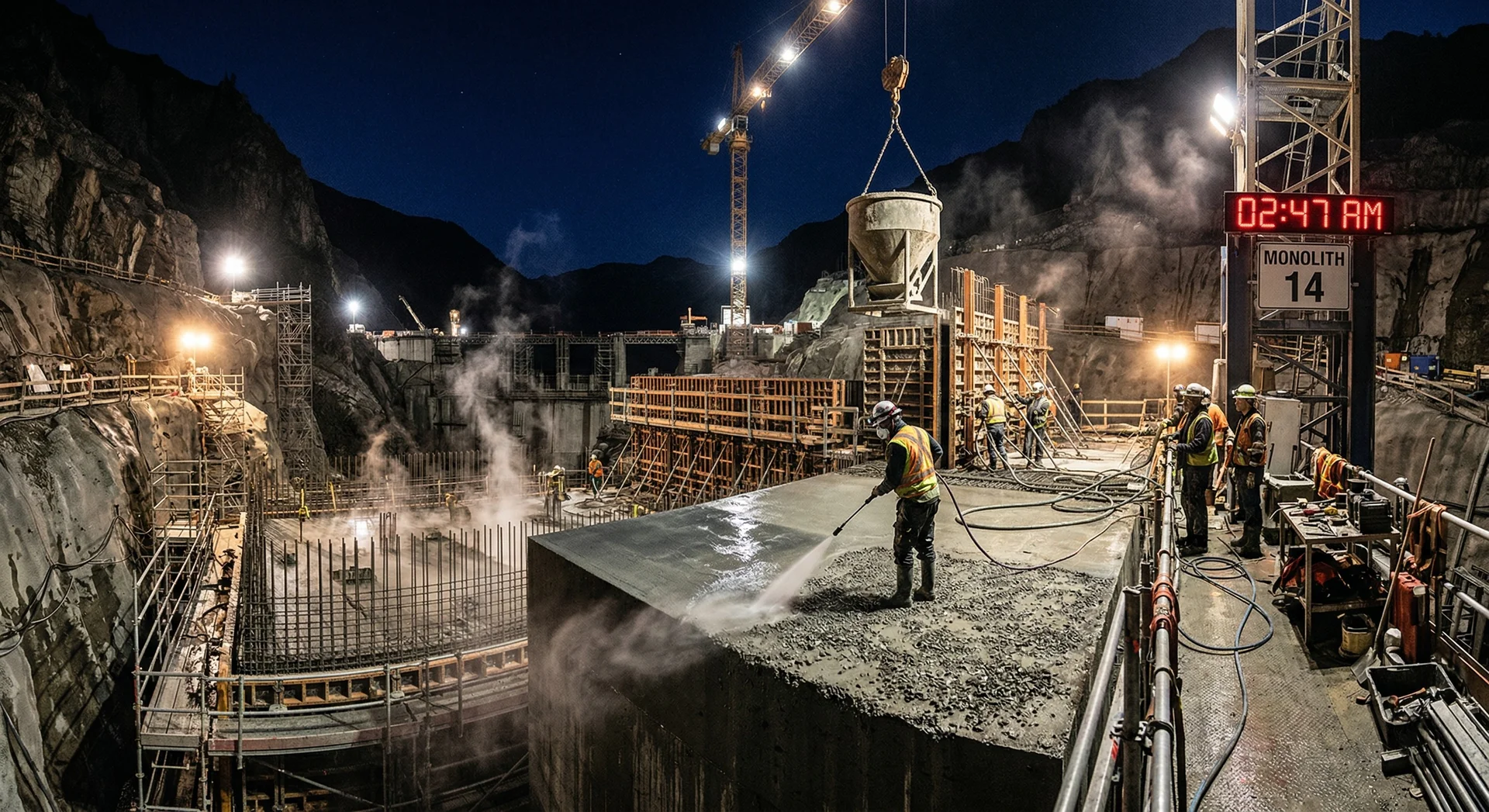
An RCC gravity dam is, by design, one of the most robust structures in civil engineering. Millions of cubic metres of compacted concrete, placed in horizontal lifts and consolidated by vibratory rollers, form a monolithic mass that resists hydrostatic pressure through sheer weight. But within that monolith lies a repeating vulnerability: the lift joint.
Every 300mm lift creates a horizontal construction joint. On a 100-metre-high dam, that translates to roughly 330 lift joints stacked from foundation to crest. In-situ core testing across RCC dams worldwide consistently reveals that joint tensile and shear strength ranges from 30-80% of the parent RCC. The variation is enormous, and the lower end of that range is where failures begin.
Why lift joints matter more than parent strength
Seepage through lift joints is the primary serviceability concern in RCC dams. ICOLD (International Commission on Large Dams) technical bulletins document that the majority of performance issues in RCC dams trace back to inadequate lift joint treatment, not to deficiencies in the parent RCC itself. A dam's watertightness is only as good as its weakest joint.
The challenge is compounded by pace. RCC construction is valued for speed: placement rates of 2,000-5,000 m³ per day are common. That speed creates pressure to keep placing lifts, sometimes at the expense of proper joint preparation. The tension between production rate and joint quality is the central quality control challenge on every RCC dam project.
Joint classification: hot, warm, and cold
The strength of a lift joint depends primarily on the maturity of the underlying surface when the next lift is placed. Industry practice, informed by ACI 207.5R and project-specific specifications, classifies joints into three categories based on elapsed time and surface condition.
| Classification | Typical Time Window | Surface Condition | Treatment Required |
|---|---|---|---|
| Hot joint | 0-6 hours (varies with temperature) | Unhardened, fresh surface. No initial set. | Minimal: surface cleaning to remove loose material and laitance. No bedding mortar needed. |
| Warm joint | 6-24 hours | Initial set has occurred. Surface is firm but not fully hardened. | Surface cleaning, moisture conditioning, and application of bedding mortar before placing next lift. |
| Cold joint | >24-48 hours | Fully hardened. Surface may have dried, carbonated, or developed a weak crust layer. | Mechanical surface preparation (green cutting or high-pressure water blasting), moisture conditioning, and bedding mortar or GERCC application. |
These time windows are approximate. The actual transition from hot to warm to cold depends on ambient temperature, humidity, wind exposure, solar radiation, and the RCC mix design itself. A lift placed in 45°C summer heat will reach initial set far faster than one placed at 10°C during winter. This is where the Modified Maturity Factor becomes essential.
Modified Maturity Factor (MMF)
Rather than relying on elapsed time alone, which is unreliable given the range of site conditions, progressive QC programs use the Modified Maturity Factor to trigger joint treatment decisions. The MMF is a cumulative time-temperature index calculated as:
MMF = Σ (Δt × T)
Where Δt is the time interval (hours) and T is the surface temperature (°C) during that interval.
Each project establishes MMF thresholds through trial placements during pre-construction. Typical values range from 500-1,000 degree-hours for the hot-to-warm transition and 1,500-3,000 degree-hours for warm-to-cold. These thresholds are calibrated against penetration resistance tests on the exposed surface and confirmed through bond strength testing of cores taken through trial joints.
Key Takeaway
Joint classification based on clock time alone is unreliable. A joint exposed for 8 hours at 40°C ambient has far more maturity than one exposed for 8 hours at 10°C. MMF-based classification removes this ambiguity, but only if the thresholds are calibrated to your specific RCC mix and your field team has the tools and training to calculate it in real time.
Joint treatment methods
Once a joint is classified, the treatment protocol must be executed precisely. Each method targets a specific failure mechanism.
Surface preparation
Every joint, regardless of classification, requires surface preparation. The goal is to remove laitance, loose particles, and any weak layer that would prevent bond between lifts.
- Air blowing: Removes loose debris. Adequate for hot joints only.
- Water jetting (low pressure): Removes surface laitance while the RCC is still green. Best performed 4-8 hours after compaction.
- Green cutting: Mechanical removal of the surface mortar layer using rotary equipment while the RCC is still semi-hardened. Exposes aggregate and creates a rough bonding surface. This is the most effective preparation for warm and cold joints.
- High-pressure water blasting: For fully hardened cold joints. Pressures of 30-70 MPa remove the weak surface layer and expose sound aggregate. Requires careful control to avoid fracturing the substrate.
Bedding mortar
Bedding mortar is a cement-sand mortar (or cement-pozzolan-sand mortar) spread over the prepared joint surface immediately before RCC placement. It fills surface irregularities, provides a paste-rich bonding layer, and compensates for the relatively lean paste content at the bottom of the fresh RCC lift.
Typical bedding mortar specifications:
- Cement:sand ratio of 1:1 to 1:2 by weight
- Fly ash substitution of 30-50% of cement, matching the RCC mix proportion
- Slump of 200-250mm (flowable consistency)
- Thickness of 6-12mm applied uniformly
- Must be placed immediately before RCC; mortar that has begun to set before RCC placement creates a double interface and weakens the bond
Grout Enriched RCC (GERCC)
GERCC is used at cold joints and along the upstream face of the dam where watertightness is paramount. A cement-sand grout is spread over the prepared surface, and the first RCC lift is placed and compacted directly onto the wet grout. The compaction energy drives the grout into the bottom of the RCC lift, creating a paste-enriched transition zone.
GERCC typically achieves 60-90% of parent RCC tensile strength at the joint, compared to 30-60% for untreated cold joints. The technique requires careful quality control: grout consistency, spread rate, coverage uniformity, and timing between grout application and RCC placement all affect performance.
The gap between specification and field reality
This is where the conversation around RCC lift joints becomes uncomfortable. The Association of State Dam Safety Officials (ASDSO) has documented ongoing debate about the disparity between design assumptions and as-built performance of RCC lift joints.
Design engineers typically assume a cohesion value and friction angle for lift joints based on laboratory-prepared specimens. These values are then used in stability analyses. The problem: laboratory-prepared joints, made under controlled conditions with ideal timing, surface preparation, and mortar application, consistently outperform field joints by significant margins.
Common field realities that degrade joint quality:
- Lifts placed after hours on exposed surfaces during hot weather, with no reclassification from hot to warm or cold
- Bedding mortar applied too early, beginning to set before RCC arrives
- Inconsistent green cutting depth or coverage
- Inadequate moisture conditioning, resulting in a dry substrate that absorbs water from the fresh RCC
- Night shift crews with less supervision executing joint treatments
- Production pressure overriding QC hold points
- Surface contamination from equipment traffic, dust, or rain
The result is a population of joints with widely variable strength. Some joints achieve 80% of parent RCC strength. Others fall below 30%. The dam’s actual factor of safety against sliding depends on the weakest joints, not the average.
The testing delay problem
Bond strength is verified by direct tensile testing of cores drilled through the lift joint. Because RCC typically contains 40-60% fly ash as a proportion of total cementitious material, strength development is slow. Cores are tested at 90, 180, or 365 days per ASTM and BIS standards. By the time a test result reveals inadequate bond, 50-200 additional lifts may already be in place. This makes process control during placement, not post-construction testing, the primary defence against joint failures.
What your QC program must cover
A robust QC program for RCC lift joints addresses four domains: classification, treatment, verification, and documentation.
1. Real-time joint classification
- Deploy surface-mounted temperature sensors on every exposed lift
- Calculate MMF continuously using automated data loggers or spreadsheet tools
- Define clear MMF thresholds validated through project-specific trial placements
- Post visible classification status at the placement face (traffic-light system: green for hot, amber for warm, red for cold)
- Empower QC personnel to halt placement if joint treatment does not match classification
2. Treatment execution and inspection
| Checkpoint | Frequency | Method | Acceptance Criteria |
|---|---|---|---|
| Surface preparation completeness | Every joint | Visual inspection + scratch test | Exposed aggregate visible; no laitance, loose material, or standing water |
| Bedding mortar thickness | Every joint | Gauge measurement at 5+ locations | 6-12mm uniform coverage |
| Mortar-to-RCC timing | Every application | Time stamp log | RCC placed within 30-45 minutes of mortar application |
| GERCC grout consistency | Every batch | Flow cone or slump measurement | Within specified range (project-dependent) |
| Moisture condition of substrate | Every joint | Visual and tactile assessment | Saturated surface dry (SSD); no free water or dry patches |
3. Bond strength verification
- Core through lift joints at defined frequency (typical: 1 core per 2,000-5,000 m² of joint area)
- Test at 90, 180, and 365 days for direct tensile strength
- Compare results against the design assumption for joint cohesion
- Maintain a running database of results by joint classification and treatment method
- Trigger formal investigation if any result falls below 70% of the design value
4. Documentation and traceability
Every lift joint must have a traceable record linking:
- Lift number, location, and placement time
- MMF at the time the next lift was placed
- Joint classification assigned
- Treatment performed (preparation method, mortar batch, application time)
- QC inspector name and sign-off
- Any deviations or non-conformances noted
- Core sample locations and test results when available
This traceability is not bureaucratic overhead. It is the dam owner’s primary evidence that the structure was built to specification. During operational reviews and dam safety inspections, regulators will ask for this data. Projects that cannot produce it face serious credibility issues.
Seepage: the consequence of poor joint quality
Seepage through lift joints is not a theoretical risk. It is the most common performance issue observed in RCC dams during initial impoundment and early operations. The mechanism is straightforward: any joint with inadequate bond or voids in the bedding mortar creates a flow path along the horizontal plane. Under hydrostatic pressure, water finds these paths.
Indicators of joint-related seepage:
- Wet spots or seepage lines visible on the downstream face, aligned horizontally
- Increased drain flows during reservoir filling
- Calcium carbonate deposits (leaching) along horizontal lines on the downstream face
- Pore pressure readings inconsistent with design assumptions
Some seepage is anticipated and managed through internal drainage systems (drainage galleries, relief wells). However, seepage beyond design limits indicates joint quality deficiencies. Progressive seepage can lead to internal erosion, particularly at joints near the foundation or at contacts between RCC and conventional concrete structures.
Key Takeaway
The cost of treating every joint properly during construction is a fraction of the cost of diagnosing and remediating seepage during operations. Grouting programs for post-construction seepage repair are expensive, disruptive, and often only partially effective. The lift joint you fail to treat correctly during a night shift may become the seepage path that triggers a dam safety review 10 years later.
Lessons from RCC dam projects
Field experience across multiple RCC dam projects in South Asia has reinforced several practical lessons about joint quality:
Production rate is not the enemy of quality, but lack of planning is. Projects that pre-plan their lift schedules around realistic MMF calculations, accounting for seasonal temperature variations, achieve both high placement rates and consistent joint quality. Projects that treat joint classification as an afterthought sacrifice quality under production pressure.
Night shifts require equal QC coverage. A disproportionate number of joint quality deficiencies occur during night shifts, when supervision is lighter and crews are less experienced. Effective programs assign dedicated QC inspectors to every shift with authority to stop placement.
Green cutting is underutilized. Many projects default to high-pressure water blasting for all cold joint preparation. Green cutting, performed at the right time (typically 4-12 hours after compaction, depending on maturity), is more effective at creating a bondable surface and is less likely to damage the substrate. The challenge is timing: it must be done within a narrow window, which requires coordination between the placement and preparation crews.
Bedding mortar quality is inconsistent. On large projects, bedding mortar is often batched in small mixers at the placement face. Without rigorous control of proportions, water content, and mixing time, batch-to-batch variability in mortar consistency translates directly to variability in joint strength. Centralised batching with quality checks at the point of application produces more reliable results.
How PCCI approaches RCC lift joint quality
PCCI’s QA/QC Systems and Lab & Testing Programs service addresses RCC lift joints as a dedicated focus area within the broader quality framework. Our approach is built on field-tested protocols developed across multiple landmark hydroelectric projects totalling 4,000+ MW.
The program covers four phases:
- Pre-construction: Establishing MMF thresholds through trial placements, calibrating surface preparation standards, developing bedding mortar and GERCC specifications tailored to the project’s RCC mix
- Construction-phase QC: Deploying real-time maturity monitoring, implementing treatment inspection checklists, training placement crews on classification protocols, and providing on-site QC supervision
- Verification testing: Designing the coring and testing program for bond strength, interpreting results against design assumptions, and triggering investigations when results fall short
- Documentation systems: Building the traceability framework that links every lift to its classification, treatment, and verification record
PCCI’s Mix Design & Performance Concrete and Construction Troubleshooting & RCA services complement this work by ensuring the RCC mix itself is optimised for joint performance and by diagnosing root causes when problems emerge.
Book a Technical Call to discuss your RCC project’s lift joint quality program.