On 11 December 1967, an earthquake of magnitude 6.6 (Mw) struck near Koyna Dam in Maharashtra. The dam, a 103-metre concrete gravity structure completed just four years earlier, suffered cracking in the non-overflow section. Approximately 180 people died in the surrounding area.
The earthquake was not purely tectonic. It was triggered, at least in part, by the reservoir itself. The impoundment of nearly 2,800 million cubic metres of water on the earth’s crust had increased pore pressure on existing geological faults, reducing the effective stress and enabling fault movement. This phenomenon, reservoir-induced seismicity (RIS), demonstrated that dams do not merely sit passively on their foundations. They interact with the geology beneath them.
For the scores of new hydropower dams planned across the Himalayas, where the Indian plate continues pushing beneath the Eurasian plate at 40-50 mm per year, the seismic design of dam concrete is not an analytical exercise. It is the difference between a structure that survives the design earthquake and one that does not.
The Seismic Environment
Tectonic Setting
The Himalayas are a collision zone. The Indian plate has been thrusting northward into the Eurasian plate for approximately 50 million years. The collision continues today, building elastic strain in the crust that is periodically released in earthquakes.
Three major fault systems define the seismic hazard:
- Main Boundary Thrust (MBT): Separates the Lesser Himalayas from the Sub-Himalayas (Siwaliks). Many dam sites are located near or on this fault system.
- Main Central Thrust (MCT): Separates the Higher Himalayas from the Lesser Himalayas. Deep-seated and capable of very large earthquakes.
- Himalayan Frontal Thrust (HFT): The southernmost active fault, where the most recent deformation is concentrated.
In addition to these major faults, countless subsidiary faults, shear zones, and lineaments traverse the region. Any dam foundation may intersect or be adjacent to active geological structures.
IS 1893 Seismic Zoning
IS 1893 divides India into four seismic zones (II through V). The Himalayan states fall predominantly in:
| Zone | Zone Factor (Z) | Peak Ground Acceleration |
|---|---|---|
| Zone IV | 0.24 | 0.24g |
| Zone V | 0.36 | 0.36g |
These zone factors represent the expected peak ground acceleration for the Maximum Considered Earthquake (MCE) with a 2% probability of exceedance in 50 years. For dam design, ICOLD and Indian practice typically require analysis for both the Operating Basis Earthquake (OBE) and the Maximum Credible Earthquake (MCE), with the MCE often exceeding IS 1893 zone factors based on site-specific seismotectonic studies.
Reservoir-Induced Seismicity
Beyond tectonic earthquakes, large reservoirs in the Himalayas must contend with RIS. The mechanism involves:
- The weight of impounded water increases vertical stress on the crust
- Elevated pore pressure from water infiltrating into fractured rock reduces effective stress on existing faults
- If the stress change is sufficient, faults that were stable under natural conditions can slip
RIS events are typically shallow (5-15 km depth) and close to the reservoir, meaning the dam experiences higher ground motion than a tectonic earthquake of the same magnitude located further away.
Koyna (1967), Nurek (Tajikistan, 1972), and Xinfengjiang (China, 1962) are documented cases. For Indian projects, Tehri Dam has been specifically identified as a potential RIS site due to the large reservoir volume and the complex geological setting. Understanding the unique concrete challenges in Himalayan hydropower requires accounting for both tectonic and induced seismicity.
How Earthquakes Load Dam Concrete
Static vs. Dynamic Loading
Under normal (static) conditions, a gravity dam resists horizontal water pressure through its own weight. The concrete is in compression throughout most of the section, with moderate tensile stresses near the upstream heel.
Under seismic loading:
- The earthquake adds horizontal inertia forces on the dam body (the mass of the dam resists the ground acceleration)
- The reservoir water exerts hydrodynamic pressure on the upstream face (the water mass also resists acceleration, pushing against the dam)
- The combined effect creates tensile stresses on the downstream face and near the dam crest that do not exist under static loading
- Vertical earthquake components can momentarily reduce the effective weight of the dam, reducing its sliding resistance
The Critical Failure Mode: Sliding
For a concrete gravity dam, the critical seismic failure mode is sliding along a horizontal plane: either a lift joint within the dam body or the dam-foundation interface.
The factor of safety against sliding depends on:
- The weight of the dam above the sliding plane (resisting force)
- The cohesion and friction coefficient at the sliding plane
- The horizontal forces from earthquake inertia and hydrodynamic pressure (driving forces)
- The uplift pressure at the sliding plane (reduces effective weight)
Under seismic loading, the driving forces increase dramatically while the resisting forces are temporarily reduced (by vertical earthquake acceleration reducing effective weight). The factor of safety drops.
If the lift joint at the critical sliding plane is a cold joint with reduced cohesion and friction, the factor of safety drops further. This is why joint quality is the single most important concrete parameter for seismic dam safety. Effective cold joint prevention and rigorous QA/QC systems are not optional in seismic zones.
Tensile Cracking
Seismic loading can create tensile stresses at the dam crest, on the downstream face, and at changes in section geometry (galleries, spillway notches). Concrete has low tensile strength (typically 5-10% of compressive strength), so seismic tensile stresses can exceed the concrete’s capacity.
Tensile cracking under earthquake loading does not necessarily mean structural failure. Gravity dams have inherent redundancy: the dam can accommodate limited cracking while maintaining overall stability through the uncracked compression zone. But extensive cracking changes the seepage pattern, reduces the effective section, and may trigger progressive deterioration under subsequent static loading. Identifying the early warning signs of concrete deterioration becomes critical for post-earthquake assessment.
Concrete Properties That Matter for Seismic Design
Tensile Strength
The dynamic tensile strength of concrete is approximately 10-20% higher than the static tensile strength due to strain rate effects. Design codes account for this through dynamic amplification factors. However, the tensile strength at lift joints does not benefit from the same amplification because the joint is a pre-existing weakness.
Shear Strength at Joints
Shear resistance at lift joints comes from:
- Cohesion: The bond strength between lifts (zero at a cold joint)
- Friction: The resistance from aggregate interlock and roughness (friction coefficient typically 0.7-1.0 for good joints, lower for cold joints)
For seismic design, both values must be established through testing of actual project concrete, not assumed from generic tables. The modified maturity method and direct shear testing of cored samples are the standard approaches. ACI 207.5R provides guidance on roller-compacted mass concrete joint testing, while site-specific durability and service-life design must account for joint degradation over the dam’s 100-year life.
Dynamic Elastic Modulus
Under rapid seismic loading, concrete behaves more stiffly than under static loading. The dynamic elastic modulus is typically 10-30% higher than the static value. This affects the natural frequency of the dam (determining which earthquake frequencies cause resonance) and the distribution of stresses within the dam body.
Damping
Concrete dams have inherent damping (energy dissipation) that reduces the dynamic response. Typical damping ratios for concrete dams: 3-5% for OBE analysis, 7-10% for MCE analysis (higher damping under stronger shaking due to micro-cracking). These values significantly affect the calculated seismic stresses and must be based on material testing or published data for similar dam concrete. The thermal control regime during construction also influences long-term concrete properties relevant to seismic performance.
Foundation Treatment for Seismic Performance
The dam-foundation interface is often the critical sliding plane, particularly for dams on jointed or weathered rock.
Consolidation Grouting
Cement grout injected into the foundation rock through a pattern of drilled holes. Purpose: fills open joints and fractures, improves rock mass modulus, reduces foundation deformability, and increases the effective cohesion at the dam-foundation interface.
For seismic design, consolidation grouting must extend to sufficient depth to ensure that the improved rock zone can resist the seismic shear forces without punching through into the untreated rock below. The U.S. Bureau of Reclamation design standards for concrete dams remain a widely referenced international benchmark for foundation treatment in seismic zones.
Curtain Grouting
A deeper grout curtain upstream of the dam reduces uplift pressure at the dam-foundation interface. Lower uplift means higher effective weight, which increases the factor of safety against seismic sliding.
In seismic zones, the grout curtain design must account for the possibility that earthquake shaking may open new fractures in the foundation, potentially compromising the curtain’s effectiveness. Redundancy in the grouting programme (multiple rows, deeper curtain) provides resilience against this risk.
Dental Concrete
Where the foundation surface is irregular, weathered, or has cavities and shear zones, dental concrete fills the voids and creates a more uniform bearing surface. For seismic loading, a uniform foundation contact is important because stress concentrations at irregular points can initiate local failure under dynamic conditions.
Foundation Drainage
A drainage curtain downstream of the grout curtain collects seepage that passes through the curtain and reduces uplift pressure. Under seismic loading, if the grout curtain is damaged by ground shaking, the drainage system provides a backup mechanism for pressure relief.
Structural Detailing for Seismic Performance
Gallery Design
Galleries create voids within the dam section, reducing the effective cross-section and creating stress concentrations at the gallery corners. Under seismic loading, the tensile stresses at gallery roof corners can exceed the concrete tensile strength.
Detailing responses:
- Reinforcement at gallery roof corners to resist tensile cracking
- Rounded corners (minimum radius 300-500 mm) to reduce stress concentration
- Gallery alignment perpendicular to the dam axis to minimise interference with the primary load path
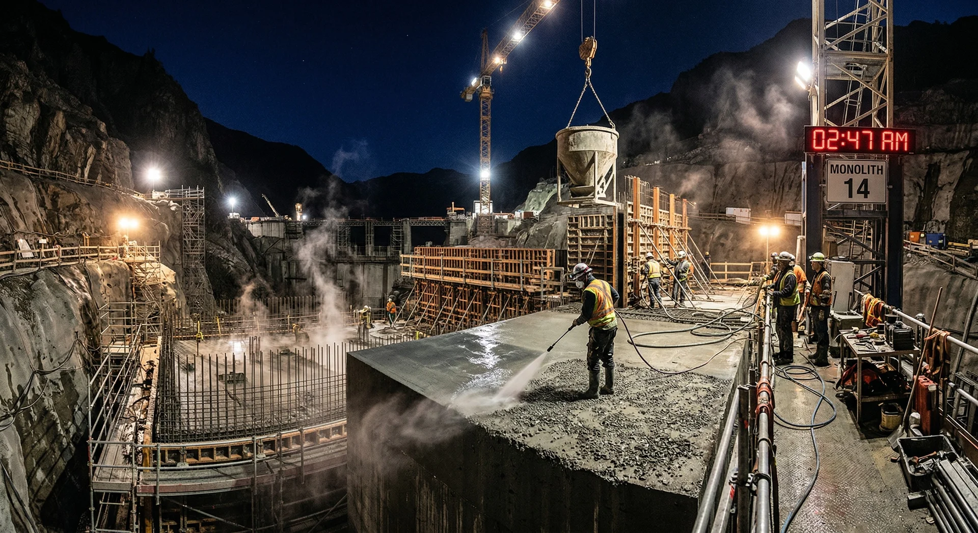
Contraction Joints
Contraction joints divide the dam into monoliths that can accommodate thermal contraction and foundation settlement independently. Under seismic loading, the relative movement between adjacent monoliths must be accommodated without damaging the waterstop or compromising the joint.
Waterstop design for seismic zones requires:
- Deformable waterstops capable of accommodating 20-50 mm of differential movement
- Redundant waterstop systems (primary and secondary)
- Joint filler material that does not lose its sealing properties under cyclic deformation
Crest and Upper Dam
The dam crest experiences the highest seismic acceleration (amplified from the base through the dam body). Crest walls, parapets, and gate structures are vulnerable to overturning and need reinforcement or mass to resist the amplified seismic forces.
Analysis Methods
Pseudo-Static Analysis
The traditional approach: applies the earthquake force as a static horizontal force equal to the seismic coefficient times the weight of the dam. Simple, conservative, and still used for preliminary design and for dams in lower seismic zones.
Limitation: does not capture the frequency-dependent dynamic response of the dam or the hydrodynamic effects accurately.
Linear Dynamic Analysis (Response Spectrum or Time History)
Uses the dam’s natural frequencies and mode shapes to calculate the dynamic response to an earthquake. Accounts for hydrodynamic pressure using the Westergaard or Chopra-Fenves approach. Standard for major dams in Zones IV and V.
Non-Linear Dynamic Analysis
For MCE evaluation of high dams in Zone V, non-linear analysis simulates the actual cracking and joint opening behaviour of the dam under strong shaking. This provides the most realistic assessment of seismic performance but requires specialised software, calibrated material models, and experienced analysts.
NCSDP 2024 and Evolving Requirements
The National Committee on Seismic Design Parameters (NCSDP) issued revised guidelines in 2024 for the seismic design of dams. Key updates include:
- Updated seismic hazard maps with higher resolution than IS 1893
- Requirements for site-specific seismic hazard assessment for all large dams in Zones IV and V
- Consideration of Maximum Credible Earthquake (MCE) based on deterministic assessment of active faults near the dam site
- Updated reservoir-induced seismicity assessment requirements
For existing dams, the Dam Safety Act 2021 mandates seismic safety assessment as part of the comprehensive evaluation. Dams designed under older seismic codes may not meet current NCSDP 2024 parameters, requiring structural assessment and potentially remedial measures. The DRIP Phase II programme provides a funding mechanism for seismic rehabilitation of aging dam infrastructure.
Key Takeaways for Dam Concrete Engineers
-
Joint quality is the seismic safety factor. The factor of safety against earthquake-induced sliding is directly proportional to the shear and tensile strength at lift joints. Every cold joint, every poorly treated construction joint, every bond failure reduces the dam’s seismic resistance.
-
Foundation treatment is not separate from seismic design. The dam-foundation interface is often the critical sliding plane. Consolidation grouting, curtain grouting, dental concrete, and drainage must be designed as seismic resistance elements, not just water control measures.
-
Dynamic properties must be tested, not assumed. Dynamic tensile strength, dynamic elastic modulus, damping ratio, and joint shear-friction parameters must come from testing of actual project concrete. A well-designed concrete lab setup and NDT testing programme are essential for establishing these values. Generic values from textbooks can underestimate or overestimate seismic response.
-
Design for the MCE, not just the OBE. The dam must survive the Maximum Credible Earthquake without catastrophic failure (uncontrolled release of the reservoir). It does not need to survive the MCE without damage, but it must survive without collapse.
-
Reservoir-induced seismicity is a real design consideration. For large Himalayan reservoirs, the dam must resist earthquakes that its own impoundment may trigger. This is not theoretical: it has happened at Koyna and is a documented concern for Tehri.
-
Seismic assessment is now mandatory under the Dam Safety Act. The Act mandates seismic safety assessment for all specified dams. Existing dams built under older codes need reassessment against current parameters. An independent review by a specialist concrete technologist can identify seismic vulnerabilities before they become regulatory non-compliance issues.
The Himalayas will shake. The question is whether the dam concrete is ready.