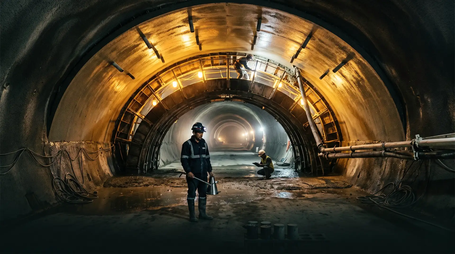
The waterway system of a hydroelectric project, comprising the headrace tunnel, pressure shaft, penstock, and tailrace tunnel, represents some of the most technically demanding concrete construction on any dam project. These structures carry water under pressure through rock masses of variable quality, over distances that can extend several kilometres.
The concrete lining serves multiple functions simultaneously. It provides a smooth hydraulic surface to minimise head losses. It prevents water from reaching and destabilising the surrounding rock. It transfers internal water pressure to the rock mass. And in steel-lined sections, it provides corrosion protection and load transfer for the steel liner.
A failure in any of these functions compromises the power station. A rough lining surface increases friction losses and reduces power output. A cracked lining injects pressurised water into rock joints, causing hydraulic jacking and potential collapse. A poorly grouted steel liner backfill allows corrosion to begin on the steel from the outside, where it cannot be inspected.
This article examines the concrete technology requirements for penstock and pressure tunnel linings, from the fundamental design decisions through placement techniques and quality control.
The Lining Design Decision
Concrete-Lined vs. Steel-Lined Sections
The first decision in pressure waterway design is which sections need steel liners and which can function with concrete lining alone. This decision has enormous cost implications: a steel-lined tunnel costs 3 to 5 times more per linear metre than a concrete-lined tunnel.
The decision is governed by the relationship between internal water pressure and the in-situ rock stress. The rock surrounding the tunnel acts as a pressure vessel. If the rock is strong, tight, and under sufficient confining stress, it can contain the internal water pressure with only a concrete lining to prevent direct contact between the water and rock surfaces.
The established criteria for this decision include:
Norwegian criterion. The minimum rock cover (overburden) must exceed the internal water pressure head, typically by a factor of 1.3 to 1.5. This ensures that the weight of rock above the tunnel exceeds the internal water pressure, preventing hydraulic fracturing of the rock. The Norwegian Confinement Criterion is described in detail in our headrace tunnel concrete article.
Minimum principal stress criterion. The minimum in-situ rock stress (measured by hydraulic fracturing tests or overcoring) must exceed the maximum internal water pressure. Where the tunnel passes through zones of low stress (near valleys, near the surface, or near geological structures), the rock cannot contain the pressure and a steel liner is required.
Rock mass permeability. Even where stress conditions are favourable, highly permeable rock may allow excessive seepage through the lining, reducing power generation and potentially causing environmental issues downstream.
The typical zoning of a hydroelectric waterway system:
| Section | Typical Lining | Reason |
|---|---|---|
| Headrace tunnel (upstream, low pressure) | Concrete only | Low pressure, adequate rock cover |
| Headrace tunnel (near powerhouse) | Steel-lined | Decreasing rock cover, increasing pressure |
| Pressure shaft (vertical or inclined) | Steel-lined | High pressure, variable rock quality |
| Penstock (surface or embedded) | Steel with concrete backfill | Maximum pressure, exposed or near-surface |
| Tailrace tunnel | Concrete only | Low pressure, gravity flow |
Concrete Lining Design
Structural Design Approaches
The structural role of the concrete lining varies depending on the design philosophy.
Load-sharing design. The concrete lining and the rock mass share the internal pressure. The lining is designed to carry a fraction of the pressure (typically 30 to 50%), with the remainder transferred to the rock through contact grouting. This is the standard approach for concrete-lined pressure tunnels in competent rock.
Per IS 4880 Part 4 (Structural Design of Concrete Lining in Rock), the design of pressure tunnel linings in India follows the Bureau of Indian Standards code for tunnels conveying water, with companion standards covering steel-lined sections (Part 7) and tunnel supports (Part 6).
Non-structural lining. The concrete lining serves only as a hydraulic surface and protection for the rock. All internal pressure is assumed to be carried by the rock mass. This approach is used in low-pressure headrace tunnels in good quality rock. The lining is typically unreinforced and 200 to 250 mm thick.
Structural lining. The concrete lining is designed to carry the full internal pressure independently, without relying on rock confinement. This is used in poor rock conditions where the rock contribution is unreliable. The lining is heavily reinforced and typically 400 to 600 mm thick.
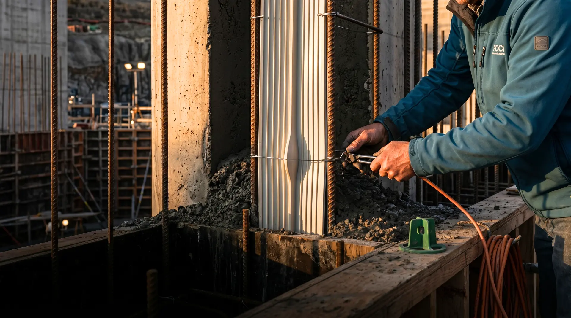
Reinforcement Design
Reinforcement in tunnel linings serves three purposes: structural resistance to internal and external pressures, crack width control, and resistance to construction-related loading (handling, temperature, and shrinkage).
| Lining Type | Reinforcement | Typical Steel Ratio |
|---|---|---|
| Non-structural (hydraulic surface only) | None or light mesh | 0.0-0.2% |
| Load-sharing (moderate pressure) | Single layer circumferential + longitudinal | 0.3-0.5% |
| Structural (full pressure capacity) | Double layer circumferential + longitudinal | 0.5-1.0% |
| Steel-lined backfill | None (steel liner carries pressure) | 0% |
Circumferential reinforcement resists hoop tension from internal pressure. Longitudinal reinforcement controls thermal and shrinkage cracking along the tunnel axis. The minimum horizontal-direction reinforcement per IS 456:2000 (Plain and Reinforced Concrete Code of Practice) Clause 32.5 is 0.20% of the gross concrete section for HYSD bars and 0.25% for mild steel bars.
Crack Width Limitations
Crack control is the defining requirement for pressure tunnel concrete linings. Unlike structural concrete in buildings, where crack widths of 0.3 mm are acceptable, pressure tunnel linings demand tighter limits to prevent pressurised water from reaching the rock.
| Pressure Head | Maximum Allowable Crack Width |
|---|---|
| Less than 30 m | 0.2 mm |
| 30-100 m | 0.15 mm |
| Greater than 100 m | 0.1 mm |
| Steel-lined backfill | 0.3 mm (non-pressure) |
These crack width limits are achieved through a combination of:
- Adequate reinforcement. Per ACI 224R-01 (Control of Cracking in Concrete Structures), the Gergely-Lutz equation or its successors relate crack width to steel stress, cover depth, and bar spacing.
- Low heat cement. Reducing the temperature rise during hydration minimises thermal cracking, the primary source of early-age cracks in tunnel linings.
- Controlled pour lengths. Limiting the length of each pour to 6 to 12 metres controls the thermal contraction that occurs as the concrete cools.
- Construction joint design. Properly designed and treated construction joints prevent cracking at the joints and ensure waterproofing continuity.
- Contact grouting. After the lining is complete, grouting fills the gap between the lining and rock, providing external pressure that tends to compress the lining and close cracks.
Concrete Mix Design for Tunnel Linings
Performance Requirements
Tunnel lining concrete must satisfy a combination of strength, durability, and workability requirements that are specific to the tunnel environment.
| Parameter | Headrace (Low Pressure) | Pressure Tunnel | Steel Liner Backfill |
|---|---|---|---|
| Compressive strength (28d) | 25-30 MPa | 30-40 MPa | 20-25 MPa |
| Water-cementitious ratio | 0.45-0.50 | 0.40-0.45 | 0.50-0.55 |
| Permeability coefficient | Less than 10⁻¹¹ m/s | Less than 10⁻¹² m/s | Less than 10⁻¹⁰ m/s |
| Slump (pumped concrete) | 100-150 mm | 100-150 mm | 75-100 mm |
| Maximum aggregate size | 20-40 mm | 20 mm | 20-40 mm |
| Heat of hydration (max) | Not critical | Low (Portland pozzolana) | Not critical |
Pumpability Requirements
Tunnel lining concrete is almost always placed by pumping. The concrete must travel through pump lines that can extend 500 metres or more from the tunnel portal to the working face, with vertical drops through shafts in some cases.
Pumpability requires:
- Adequate paste volume. The paste (cement + water + fine material) must exceed 40% by volume to lubricate the aggregate and prevent blockage.
- Continuous grading. No gaps in the aggregate grading curve that would cause segregation under pumping pressure.
- Appropriate slump. Typically 100 to 150 mm at the pump, accounting for slump loss during transit through the pipeline.
- Pumping aid admixtures. Viscosity-modifying admixtures can improve pumpability without increasing water content.
The pipeline friction loss must be calculated and the pump capacity specified accordingly. Per ACI 304.2R-17 (Guide to Placing Concrete by Pumping Methods), friction losses in horizontal pipe are approximately 0.2 to 0.7 MPa per 100 metres for conventional concrete, and higher for the low w/c mixes used in pressure tunnel linings.
Temperature Considerations
Tunnel lining concrete is placed in an environment with relatively constant temperature (the rock temperature, typically 15 to 30 degrees Celsius in India depending on depth). However, the lining thickness of 200 to 500 mm is sufficient for cement hydration to generate meaningful temperature rise in the centre.
For a 400 mm thick lining with a cementitious content of 350 kg/m³, the temperature rise at the centre can reach 15 to 25 degrees Celsius above the placement temperature. As the concrete cools back toward the rock temperature, it contracts. If restrained by the previously placed concrete, this contraction induces tensile stress that can cause circumferential cracking.
Mitigation measures:
- Low-heat cementitious system. Use Portland Pozzolana Cement (PPC) or OPC with 30 to 40% fly ash or GGBS, drawing on the broader thermal control framework for mass concrete and SCM strategies.
- Controlled pour length. Shorter pours (6 metres) reduce the volume of concrete that must cool, reducing the magnitude of thermal contraction.
- Timing of contact grouting. Delaying contact grouting until the lining has completed most of its thermal contraction (typically 60 to 90 days after placement) ensures that the grout fills the final gap and the lining does not subsequently separate from the grout.
Placement Methods
Travelling Form (Shuttering Gantry)
The standard method for placing tunnel lining concrete. A collapsible steel form, shaped to the tunnel profile, is set at the working location. Concrete is pumped into the form through ports, filling from the bottom up.
Sequence for a typical D-shaped tunnel:
-
Invert pour. The tunnel floor (invert) is placed first as a separate operation, using conventional formwork. The invert is levelled to the design profile and cured.
-
Sidewall and arch pour. The travelling form is set on the cured invert. Concrete is pumped through ports in the form, starting at the lowest point of the sidewalls and progressing upward. The form is filled in balanced layers (equal height on both sides) to prevent lateral pressure imbalance.
-
Crown pour. The final concrete is placed through the crown of the form via ports or windows. This is the most critical placement: air must escape as the concrete fills the last space. Vent pipes in the crown of the form allow air to escape. The concrete must be fluid enough to fill the crown completely, as any void creates an ungrouted zone.
-
Form stripping. After the concrete has gained sufficient strength (typically 12 to 24 hours for non-structural linings, longer for structural linings), the form is collapsed inward and advanced to the next position.
-
Curing. The exposed concrete surface is cured by misting, ponding on the invert, or application of curing membrane on non-hydraulic surfaces.
Slip-Form Systems
For long, straight tunnel sections with constant cross-section, slip-forming produces a continuous lining without construction joints. The form moves continuously at a rate of 1 to 3 metres per hour, with concrete placed continuously at the trailing edge.
Advantages: no construction joints (which are potential leakage points), higher daily production rate, better surface quality.
Disadvantages: requires consistent concrete supply (any interruption damages the lining), limited to constant cross-sections, higher equipment cost, requires experienced crews.
Concrete Backfill for Steel Liners
The annular space between a steel penstock pipe and the rock excavation is filled with concrete (backfill) to transfer loads and protect the steel. The backfill placement presents unique challenges:
- Limited access. Concrete can only enter through holes (typically 100 to 150 mm diameter) drilled in the steel pipe.
- One-sided form. The steel pipe is the inner form; the rock is the outer form. Neither is adjustable.
- No vibration. Mechanical vibration can damage the steel pipe alignment and welds. Self-compacting concrete (SCC) or highly flowable mixes are required.
- Crown filling. The space at the crown of the pipe is the last to fill and the most difficult to reach. Multiple grout holes along the crown allow air to escape and concrete to fill.
The backfill concrete mix is typically:
| Parameter | Specification |
|---|---|
| Compressive strength | 20-25 MPa at 28 days |
| Slump flow (SCC) | 550-650 mm |
| Maximum aggregate size | 20 mm |
| Segregation resistance | Stable at flowable consistency |
| Heat of hydration | Low (to prevent thermal damage to steel pipe) |
After the backfill concrete has cured and shrunk, contact grouting is performed through the same holes used for backfill placement, filling the gap that forms between the hardened concrete and the rock surface.
Grouting Programme
Contact Grouting
Contact grouting is essential for both concrete-lined and steel-lined pressure tunnels. Its purpose is to fill the gap between the concrete lining (or concrete backfill) and the surrounding rock.
Timing. Contact grouting should not be performed until the concrete lining has completed most of its thermal contraction and early shrinkage. The minimum wait period is typically:
- 28 days for thin linings (less than 250 mm) in moderate temperatures
- 60-90 days for thick linings (greater than 300 mm) or in warm conditions where higher temperature rise delays cooling
- After all upstream and downstream sections are complete, to prevent grouting pressure from damaging adjacent fresh concrete
Grout mix. Neat cement grout with a water-cement ratio of 0.5 to 0.8 by weight. Bentonite (2 to 5% by weight of cement) may be added for stability. Superplasticiser reduces the water-cement ratio for higher strength grout.
Pressure. Contact grouting pressures are kept low to avoid cracking the concrete lining: typically 0.1 to 0.3 MPa above the groundwater pressure. Higher pressures can lift the lining off the rock, creating new gaps.
Grout holes. Pre-installed during lining placement, typically 25 mm diameter steel pipes cast into the concrete at 2 to 3 metre intervals along the tunnel crown. In D-shaped tunnels, holes are also placed at the spring line (sidewall-arch junction) where gaps are common.
Acceptance criteria. Contact grouting continues at each hole until refusal is achieved at the specified pressure (typically when the grout take drops below 0.5 litres per minute sustained for 5 minutes) or until a specified maximum volume has been injected.
Consolidation Grouting
After contact grouting, consolidation grouting may be performed through the lining to improve the quality of the rock mass immediately surrounding the tunnel. This is particularly important for pressure tunnels where the rock must contain the internal pressure.
Consolidation grout holes are drilled through the concrete lining into the rock, typically to a depth of 3 to 5 metres. Cement grout is injected at pressures determined by the rock conditions and the internal operating pressure.
Per USACE EM 1110-2-2901 (Tunnels and Shafts in Rock) and broader international practice, the grouting programme for pressure tunnels should be designed to reduce the rock mass permeability to less than 1 to 3 Lugeon units in the zone immediately surrounding the tunnel.
Quality Control
Concrete Quality
Standard quality control for tunnel lining concrete follows IS 456:2000 and project-specific specifications. The key parameters monitored include:
| Parameter | Test Method | Frequency |
|---|---|---|
| Compressive strength | IS 516 (cube test) | 1 set per pour (minimum) |
| Slump | IS 1199 | Every batch |
| Temperature | Thermometer | Every batch |
| Air content (if specified) | IS 1199 Part 6 | Every batch |
| Unit weight | IS 1199 | Every pour |
| Permeability (on cores) | IS 3085 | Per tunnel section or per 100 m |
Lining Quality
Beyond concrete material quality, the lining itself must be assessed for:
- Thickness. Measured by core drilling or ground-penetrating radar (GPR). Lining thickness less than the design minimum requires engineering evaluation and possible remedial action.
- Voids behind the lining. Detected by hammer sounding, GPR, or impact-echo testing. Voids indicate incomplete grouting or concrete placement deficiencies.
- Surface quality. The hydraulic surface must be smooth and free from significant irregularities that increase friction losses. Surface tolerance of plus or minus 10 mm under a 3 metre straightedge is typical for headrace tunnels, tighter for high-velocity sections.
- Crack survey. All visible cracks are mapped, measured for width, and classified as structural or non-structural. Cracks exceeding the allowable width for the operating pressure are sealed by injection.
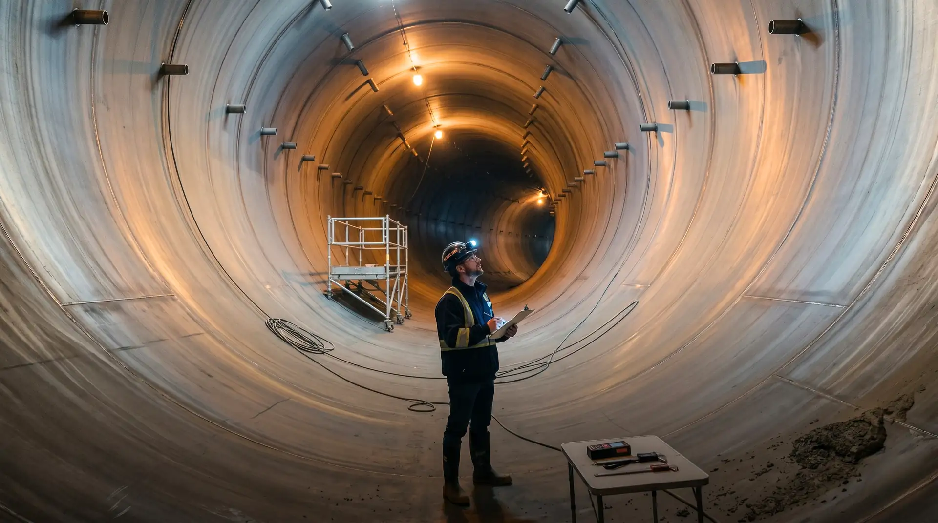
Hydrostatic Testing
Before commissioning, pressure tunnels undergo hydrostatic testing to verify lining integrity. The tunnel is filled with water and pressurised to the design operating pressure (or a test pressure of 1.25 to 1.5 times operating pressure). Seepage is measured by monitoring the water level or pressure over a specified period.
Acceptance criteria vary by project, but typical limits are:
- Seepage less than 1 litre per minute per 100 metres of tunnel for concrete-lined sections
- No increase in seepage over the test period (indicating the lining is not deteriorating under pressure)
- No displacement of the lining measured by convergence monitoring points
If the test fails, the tunnel is drained, leakage locations are identified and repaired, and the test is repeated.
Common Problems and Solutions
Crown Voids
The most common construction deficiency in tunnel linings: incomplete concrete filling at the crown of the arch. The void forms because air becomes trapped as the rising concrete reaches the top of the form, and the concrete is too stiff to flow laterally and push the air toward the vent points.
Prevention: use higher-slump concrete for the crown pour (150 mm slump or SCC), provide adequate vent holes in the form (at 1 to 2 metre intervals along the crown), and pump concrete through multiple crown ports rather than relying on a single injection point.
Repair: if discovered by hammer sounding or GPR after form removal, the void can be filled by drilling through the lining and injecting cement grout or flowable mortar.
Thermal Cracking
Circumferential cracks caused by thermal contraction are common in tunnel linings, particularly in thick linings (greater than 300 mm) with high cement content. These cracks can become leakage paths under pressure.
Prevention: use low-heat cementitious systems, limit pour lengths, and provide sufficient longitudinal reinforcement for crack width control. Per ACI 207.2R (Effect of Restraint, Volume Change, and Reinforcement on Cracking), the temperature difference between the peak hydration temperature and the final stable temperature determines the thermal strain. Reinforcement must limit the resulting crack width to the specified maximum.
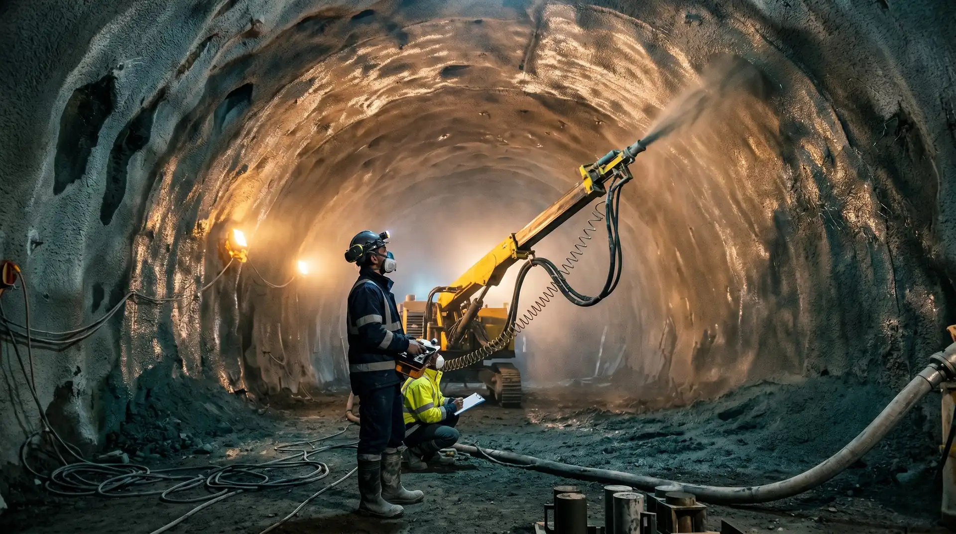
Groundwater Inflow During Construction
Groundwater flowing through the rock into the tunnel during lining construction contaminates the concrete, weakens the bond between the lining and rock, and can wash cement from fresh concrete. High groundwater inflow must be controlled before lining placement by pre-grouting the rock from probe holes ahead of the tunnel face, often combined with shotcrete primary support on heavily-fractured zones.
Conclusion
Pressure tunnel and penstock linings represent a convergence of concrete technology, geotechnical engineering, and hydraulic design. The concrete must perform as a structural element, a hydraulic surface, and a waterproofing barrier simultaneously, and its quality must be maintained over kilometres of tunnel in conditions that are dark, confined, and often wet.
The keys to successful tunnel lining concrete are mix design that balances strength, permeability, and thermal performance; placement methods that achieve complete filling without vibration damage to formwork or adjacent structures; crack control through reinforcement, pour sequencing, and thermal management; and a grouting programme that seals the lining to the rock and the rock to itself.
When these elements are executed correctly, the waterway system delivers water to the turbines at the design pressure and flow rate, reliably, for the full service life of the project. When any element fails, the consequences range from chronic seepage losses that reduce power generation to catastrophic tunnel failures that shut down the power station entirely.
How PCCI approaches pressure tunnel and penstock concrete
Pressure waterways are part of every project in PCCI’s 4,000+ MW portfolio, from the headrace and penstock systems at Karchham Wangtoo (1,000 MW) and Tala (1,020 MW) through the high-pressure shafts at Mangdechhu (720 MW). The framework outlined above is shaped by what these projects taught us about Himalayan rock, monsoon construction windows, and the long-term consequences of small lining defects.
Our mix design service addresses the strength, permeability, pumpability, and thermal-control balance that pressure tunnel concrete demands. Our thermal control service handles the heat-of-hydration and crack-control programme for thick linings. Our QA/QC service covers the pour-by-pour discipline (slump, temperature, cube sampling, permeability cores) that determines whether a tunnel passes its hydrostatic test on the first attempt.
Book a Technical Call → to discuss your project’s pressure tunnel and penstock concrete requirements.