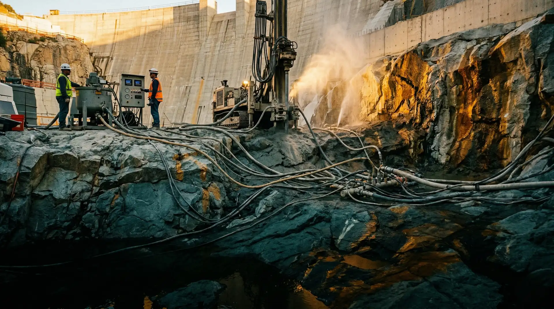
The first thing that happens after a hydropower tunnel is excavated is that the rock starts to move.
The excavation removes the rock that was providing support. The surrounding rock mass, under the stress of the overburden above and the tectonic forces within the mountain, begins to deform inward. Blocks loosen along joints and fractures. In poor rock, the entire tunnel profile can squeeze inward by centimetres or even metres if unsupported.
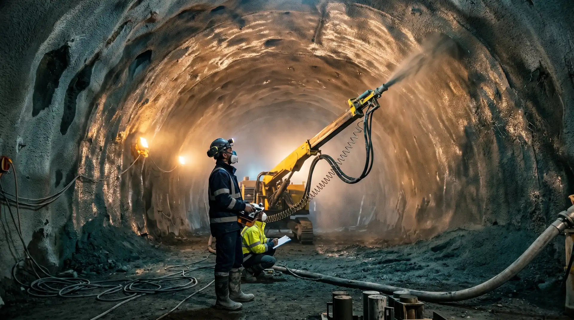
Shotcrete is the immediate response. Within hours of excavation, a layer of fibre-reinforced concrete is projected onto the rock surface at high velocity. The shotcrete bonds to the rock, bridges fractures, supports loosened blocks, and creates a structural shell that resists the inward deformation. It is the first line of defence against tunnel collapse, and in many modern hydropower projects, it is also the permanent lining.
India’s hydropower pipeline includes hundreds of kilometres of tunnels: headrace tunnels, tailrace tunnels, surge shafts, access tunnels, and construction adits. The Tehri PSP alone has multiple tunnels ranging from 932 to 1,255 metres. Pinnapuram has six penstocks at 760 metres each. Snowy 2.0 in Australia involves 27 kilometres of tunnelling between the Tantangara and Talbingo reservoirs. In each case, the shotcrete quality determines whether the tunnel functions as a durable conduit or a perpetual maintenance problem.
Wet-Mix vs. Dry-Mix: The Industry Has Decided
Two methods exist for projecting shotcrete:
Dry-mix: The dry ingredients (cement, aggregate, fibres) are conveyed by compressed air through a hose. Water is added at the nozzle by the operator, who controls the water content in real time.
Wet-mix: All ingredients including water, admixtures, and fibres are mixed in a conventional mixer. The complete mix is pumped through a hose, and compressed air is added at the nozzle for projection.
The industry has decisively moved to wet-mix for hydropower tunnel applications:
| Parameter | Dry-Mix | Wet-Mix |
|---|---|---|
| Dust generation | High | Low |
| Rebound (waste) | 15-30% | 5-15% |
| Quality consistency | Operator-dependent (water control) | Batch-controlled |
| Production rate | 3-5 m3/hour | 8-20 m3/hour |
| Fibre distribution | Difficult | Uniform |
| Working environment | Dusty, poor visibility | Cleaner, safer |
Dry-mix remains useful for small-volume applications, repair work, and situations where the delivery distance from the mixer to the nozzle is very long. For systematic tunnel lining on hydropower projects, wet-mix is the standard.
Fibre Reinforcement: Replacing the Mesh
Traditional shotcrete reinforcement used welded wire mesh installed against the rock surface before shotcrete application. The mesh had to be cut, shaped to the tunnel profile, fixed to the rock with pins or bolts, and then covered with shotcrete from both sides.
This approach had fundamental problems:
- Safety: Workers installing mesh on freshly excavated, potentially unstable rock faces were exposed to rockfall hazards.
- Quality: Achieving full encapsulation of the mesh within the shotcrete was difficult. Voids behind and around the mesh wires were common, creating corrosion initiation sites.
- Time: Mesh installation added hours to the support cycle, leaving the rock unsupported longer.
- Shadow zones: Shotcrete could not penetrate behind the mesh at some angles, leaving unsupported rock.
Fibre-reinforced shotcrete (FRS) eliminates all of these problems. Fibres are mixed into the wet shotcrete and applied in a single operation. The tunnel receives immediate, continuous, three-dimensional reinforcement as soon as the shotcrete is projected.
Steel Fibres
The standard for structural FRS in tunnels:
- Type: Hooked-end or deformed cold-drawn wire
- Length: 25-60 mm (length-to-diameter ratio of 45-80)
- Diameter: 0.5-1.0 mm
- Dosage: 25-50 kg/m3 (structural applications typically 30-40 kg/m3)
- Material: Low-carbon steel, sometimes with corrosion-resistant coating
Hooked-end fibres provide the best anchorage in the concrete matrix: the hooks engage with the paste and aggregate, preventing the fibre from pulling out under load. This pull-out resistance is what gives FRS its post-crack ductility: after the concrete cracks, the fibres bridge the crack and continue to carry load.
Synthetic Fibres
Used for specific applications:
- Macro synthetic fibres (40-60 mm polypropylene or polyolefin): Provide ductility similar to low-dose steel fibres. Advantages: no corrosion risk, lighter weight. Used where long-term corrosion is a concern (aggressive groundwater, marine tunnels).
- Micro synthetic fibres (12-18 mm polypropylene): Added at low dosage (0.6-1.0 kg/m3) to reduce plastic shrinkage cracking in the first hours after application. Not structural.
Performance Classification
FRS performance is classified by the energy absorption capacity of the shotcrete, measured by the ASTM C1550 round panel test or the BS EN 14488-5 square panel test. The energy absorption (in Joules) at specified deflections defines the shotcrete class.
Typical requirement for hydropower tunnels: Energy absorption of 500-1,000 Joules at 40 mm deflection in the round panel test (ASTM C1550). Higher energy classes for poor rock or high-stress conditions.
Shotcrete Mix Design for Hydropower Tunnels
Target Properties
| Property | Initial Support | Permanent Lining |
|---|---|---|
| 8-hour strength | 1-3 MPa | Not critical |
| 24-hour strength | 5-10 MPa | 5-10 MPa |
| 7-day strength | 20-25 MPa | 20-25 MPa |
| 28-day strength | 30-40 MPa | 35-50 MPa |
| Fibre dosage | 30-40 kg/m3 steel | 30-40 kg/m3 steel |
| Water-cementitious ratio | 0.42-0.48 | 0.40-0.45 |
| Cementitious content | 400-450 kg/m3 | 420-480 kg/m3 |
| Maximum aggregate size | 10-12 mm | 10-12 mm |
Key Mix Design Considerations
Aggregate size: Maximum 10-12 mm for wet-mix shotcrete. Larger aggregate increases rebound and creates shadow zones. Well-graded aggregate with sufficient fines (passing 0.15 mm: 4-8%) is essential for pumpability and reduced rebound.
Cementitious content: Higher than conventional concrete (400-480 kg/m3 vs. 250-350 kg/m3) because the fine aggregate fraction must be partially compensated by cement paste for pumpability and adhesion.
Silica fume: 5-10% of cementitious content. Improves adhesion (critical for overhead application), reduces rebound, increases density and impermeability, and improves early strength. Silica fume is nearly universal in modern tunnel shotcrete.
Accelerator: Alkali-free liquid accelerator added at the nozzle (3-8% of cementitious content). Provides rapid initial set (less than 3 minutes) and early strength development. Modern alkali-free accelerators reduce long-term strength loss to less than 10-15%, a significant improvement over older alkali-based accelerators.
Superplasticiser: Essential for achieving the required pumpability at low water-cementitious ratios. Dosage: 0.8-1.5% of cementitious content.
SCMs: Fly ash (15-25%) can be used to reduce heat generation and cost, but it slows early strength development. GGBS (20-30%) provides better early strength than fly ash while still reducing heat. The choice depends on early strength requirements and material availability, and is covered in detail in our SCM strategies for dam concrete article.
Application: The Nozzle Operator’s Art
Despite advances in robotic application, shotcrete quality still depends significantly on the skill of the nozzle operator:
Distance and Angle
Optimum distance: 1.0-1.5 metres from nozzle to surface. Closer causes excessive rebound. Further reduces compaction energy and increases material loss.
Optimum angle: Perpendicular to the surface. Angled application increases rebound and creates voids behind protruding rock features.
Layer Thickness
Shotcrete should be applied in layers of 50-75 mm per pass. Applying thicker layers in a single pass risks:
- Sagging and sloughing on walls and crown (gravity pulls the wet shotcrete down)
- Trapping rebound material within the shotcrete layer
- Incomplete compaction of the inner portion
For a 150 mm design thickness, apply in 2-3 passes with each pass achieving full compaction before the next is applied.
Overhead Application
The crown (top) of the tunnel is the most challenging area. Gravity works against adhesion, and the risk of fallback (freshly applied shotcrete falling from the overhead surface) is highest. Solutions:
- Silica fume in the mix (improves cohesion and adhesion)
- Higher accelerator dosage at the nozzle for overhead passes
- Thinner individual layers (40-50 mm per pass overhead)
- Continuous circular motion to maintain even buildup
Robotic Application
Robotic shotcrete arms (mounted on a mobile carrier with programmable nozzle positioning) provide consistent distance, angle, and layer thickness control that manual nozzling cannot match. Robotic application reduces rebound to 3-8%, improves thickness uniformity, and increases production rate to 15-20 m3/hour.
For large hydropower tunnels with systematic shotcrete lining, robotic application is the standard. Manual nozzling is reserved for irregular surfaces, small cross-sections, and localised repairs.
Quality Control
Early Strength Testing
Penetrometer test (Hilti method): A calibrated spring-loaded needle is pushed into the young shotcrete at defined ages (1, 3, 6, 8, 12, 24 hours). The penetration depth correlates with compressive strength. This test verifies that the accelerator is working and the shotcrete is gaining strength fast enough to support the rock.
Minimum requirements:
- 0.5-1.0 MPa at 6 hours (safe for personnel re-entry)
- 1.0-3.0 MPa at 8 hours (supporting rock load)
- 5.0-8.0 MPa at 24 hours (adequate for most rock classes)
Thickness Verification
Probe drilling: Short holes drilled through the shotcrete to the rock surface. The drill bit penetration depth minus the probe hole depth in rock gives the shotcrete thickness. Testing frequency: typically every 10-25 metres of tunnel length, at crown, shoulder, and wall positions.
Alternative: Pre-installed thickness pins (markers placed on the rock surface before shotcrete application) checked after shotcrete cures.
Core Testing
Cores extracted from the applied shotcrete at 28 days for:
- Compressive strength (per IS 516 or EN 12504-1)
- Fibre content verification (by magnetic separation or visual count)
- Bond strength at the shotcrete-rock interface (if the core includes the contact)
- Visual examination for voids, laminations, and rebound inclusions
Panel Testing
Energy absorption testing of fibre-reinforced shotcrete using panel tests:
- Round panel test (ASTM C1550): A 75 mm thick, 800 mm diameter circular panel supported on three points, loaded at the centre. Energy absorbed to failure and at 40 mm deflection is recorded.
- Square panel test (EN 14488-5): A 75-100 mm thick, 600x600 mm panel similarly loaded.
Panel tests verify that the fibre dosage and distribution produce the required post-crack ductility. Panels are typically cast alongside the tunnel application (sprayed into a mould at the same time and with the same mix).
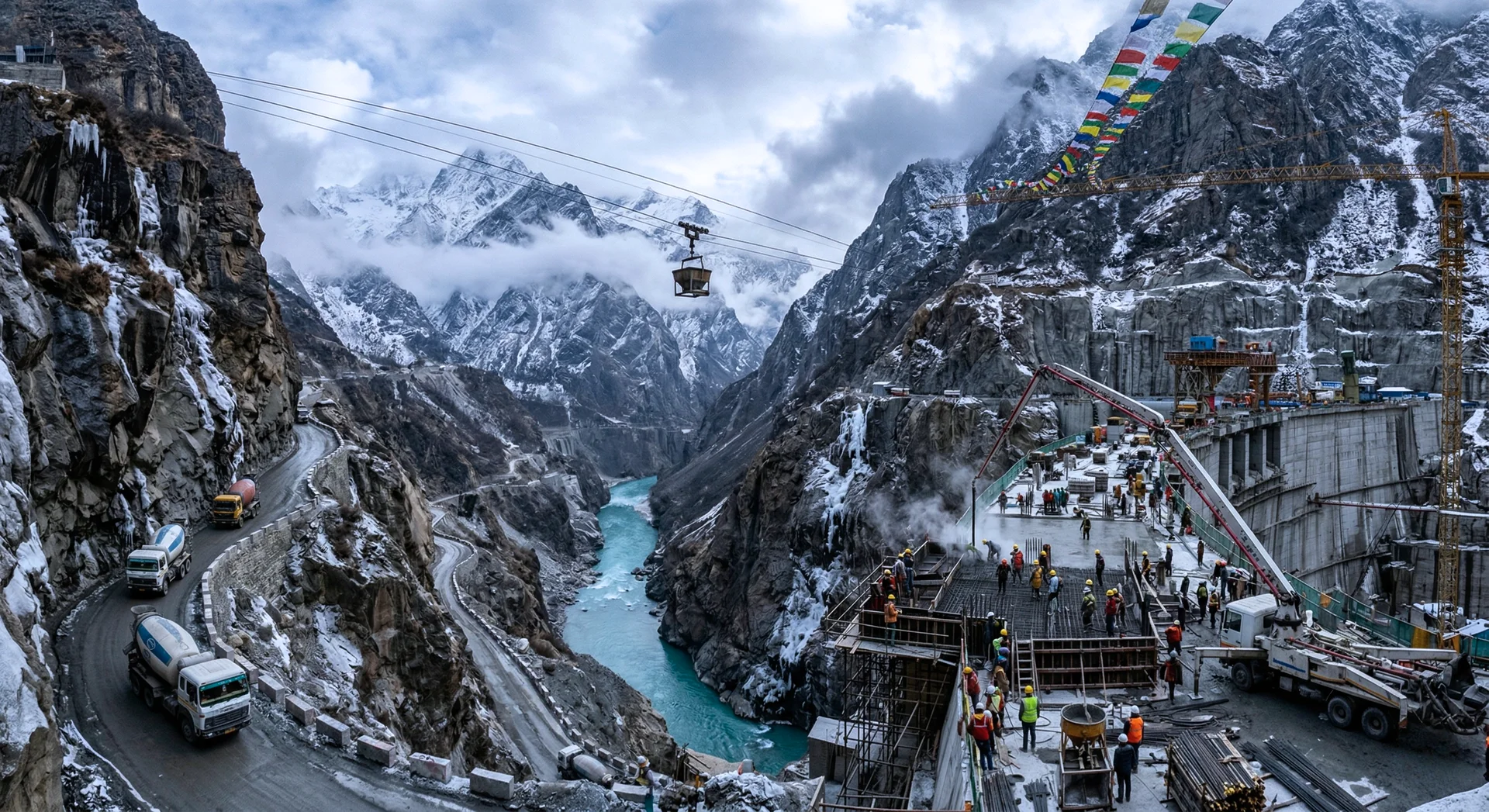
Tunnel-Specific Challenges in Himalayan Hydropower
Squeezing Ground
In high-overburden tunnels through weak rock (common in the Lesser Himalayas), the rock mass squeezes inward under the overburden stress. Conventional shotcrete, which is stiff and brittle, can crack under the squeezing deformation.
Response: Compressible shotcrete layers (using compressible inclusions or yielding elements) that allow controlled deformation while maintaining support. Or sequential shotcrete application: an initial thin layer that deforms with the rock, followed by a thicker structural layer after the deformation stabilises.
Tehri PSP experienced squeezing rock conditions and major cavity formation in surge shafts, requiring adaptable shotcrete and concrete strategies.
Water Inflow
Many Himalayan tunnels encounter significant groundwater inflow. Shotcrete applied to surfaces with active water flow does not bond properly: the water washes away the cement paste before it can set.
Response: Pre-grouting to reduce water inflow before shotcrete application. Flash-set shotcrete (very high accelerator dosage) for localised wet areas. Drainage provisions (weep holes, drainage fleece) behind the shotcrete to relieve hydrostatic pressure.
Aggressive Groundwater
Some Himalayan rock formations contain sulphate-bearing minerals or acidic groundwater that attacks cement paste. Standard shotcrete may deteriorate rapidly in these conditions.
Response: Sulphate-resistant Portland cement (IS 12330) or equivalent. GGBS or fly ash replacement at 20-40% to improve sulphate resistance. Reduced permeability through silica fume and low w/c ratio.
The Quality Hierarchy
In tunnel shotcrete, quality is determined by a hierarchy of factors:
- Mix design provides the potential quality (strength, durability, fibre content)
- Application determines how much of that potential is achieved (nozzle technique, thickness, compaction)
- Accelerator dosage controls the early strength (too little: unsafe; too much: long-term strength loss)
- Curing conditions in the tunnel (humidity, temperature, ventilation) affect strength development
- QC testing verifies that the achieved quality meets the specification
Each level can only maintain or reduce the quality established by the level above. A perfect mix design poorly applied produces poor shotcrete. A good application of a poor mix design produces poor shotcrete. Quality must be right at every level.
The shotcrete lining of a hydropower tunnel is not visible once the project is operational. Water flows through it, pressure acts on it, and rock loads bear on it for decades without inspection. Getting the shotcrete right during construction is the only opportunity. There is no second chance once the tunnel is commissioned.
How PCCI approaches shotcrete tunnel concrete
Underground works are part of every project in PCCI’s 4,000+ MW portfolio, from the headrace and tailrace tunnels at Tala (1,020 MW) and Karchham Wangtoo (1,000 MW) through the surge shafts and pressure tunnels at Punatsangchhu-1 (1,200 MW). Each project has shaped the shotcrete framework we apply today.
Our mix design service addresses the wet-mix shotcrete recipe (cementitious content, silica fume, alkali-free accelerator, fibre type and dosage) for the specific rock and groundwater conditions on the project. Our QA/QC service covers early-strength penetrometer testing, panel-test energy absorption, thickness verification, and core extraction. Our troubleshooting service handles the recurring shotcrete defects (delamination, fallback at the crown, water-driven washout, inadequate fibre distribution) that appear during long tunnel drives.
Book a Technical Call → to discuss your project’s shotcrete tunnel lining requirements.