The artery of every hydropower project
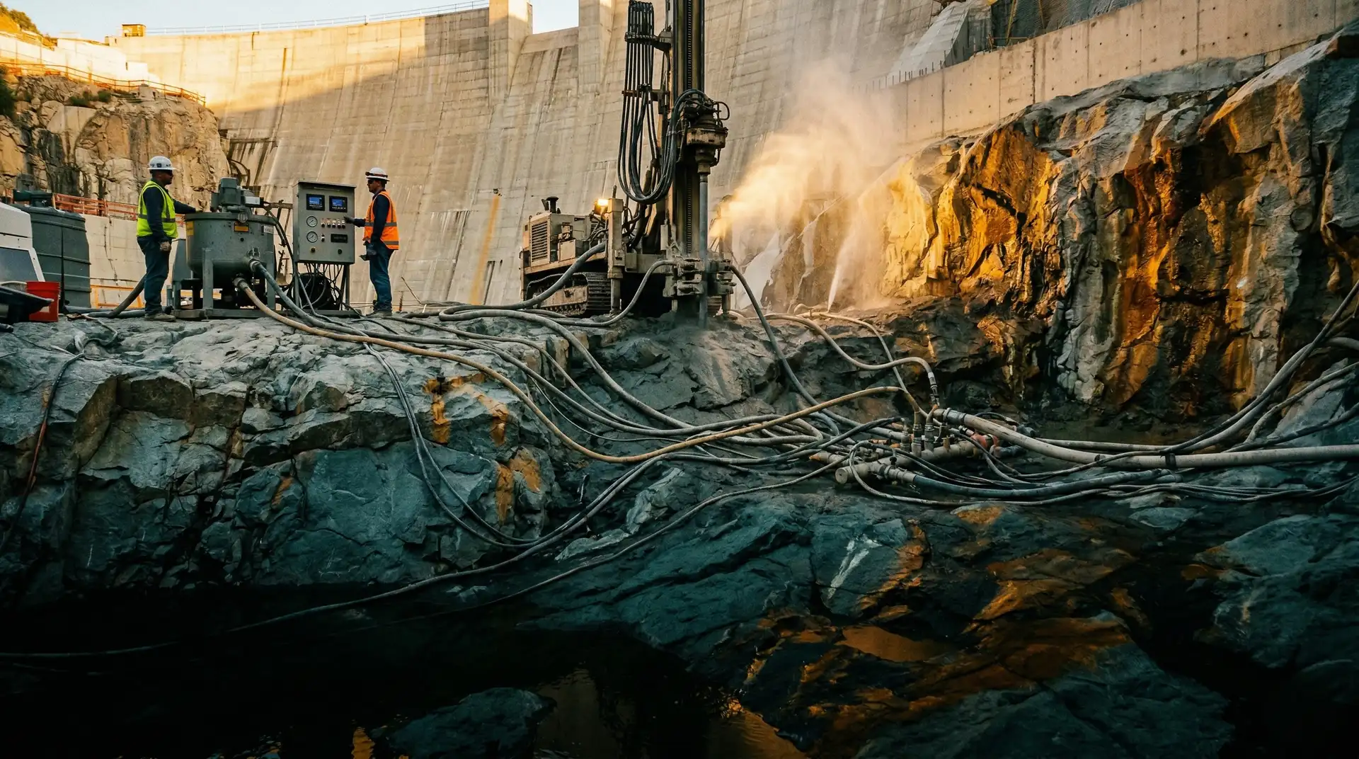
A headrace tunnel is not a structure that fails dramatically. It fails slowly, through small cracks that grow into seepage paths, through chemical attack that thins the lining, through cold joints that open under cyclic water pressure. By the time the failure is visible, the project is already losing head, losing generation, and losing the ability to dewater the tunnel for repair without losing weeks of revenue.
The concrete lining of a headrace tunnel typically represents 8 to 15% of total civil works cost on a hydropower project. The cost of remediating a failed lining mid-life can exceed that figure several times over, including the lost generation during dewatering and the structural risk to the surrounding rock mass.
This is the single most under-documented discipline in Indian hydropower construction. Most field engineers learn it through apprenticeship, not from standards. The two governing references, IS 5878 (Code of Practice for Construction of Tunnels Conveying Water) and IS 4880 (Code of Practice for Design of Tunnels Conveying Water), were last comprehensively revised in the 1970s. They are still the legal reference, but practice has moved well beyond what they cover.
Lining types and selection logic
The first design decision for a headrace tunnel is whether it needs a lining at all, and if so, what kind. The choice depends on rock quality, internal pressure, head loss economics, and project life expectancy.
| Lining type | Where it works | Where it fails |
|---|---|---|
| Unlined rock | Competent, low-permeability rock with high confinement, low pressure | Permeable, weathered, or fractured rock; high pressure; seismic zones |
| Shotcrete only (75 to 150 mm) | Fair to good rock; primary support converts to permanent; low pressure | High pressure tunnels; long-term durability concerns; uneven hydraulic surface |
| Plain concrete lining (250 to 400 mm) | Moderate rock conditions; non-pressure or low-pressure tunnels | High internal pressure where reinforcement is needed |
| Reinforced concrete lining (300 to 500 mm) | High-pressure sections; weak or weathered rock; seismic zones | Where steel liner economics are favourable |
| Steel liner with concrete backing | Very high internal pressure; minimum rock cover violated; sensitive surface assets | Where rock conditions allow lower-cost alternatives |
Norwegian hydropower has shown that unlined or partially lined headrace tunnels can perform reliably for over a century when rock conditions are right. The Norwegian Confinement Criterion, which requires the minimum principal rock stress at the tunnel periphery to exceed the internal water pressure with a typical safety factor of 1.3, is now part of international practice referenced by the International Tunnelling Association for unlined pressure tunnels.
Indian practice has historically been more conservative. Most Indian and Bhutanese hydropower headrace tunnels are fully concrete lined, partly because of variable rock quality in the Himalayas, partly because of contractual risk allocation, and partly because of construction culture. The trend over the last decade has shifted toward selective lining: full concrete lining where pressure or rock quality demand it, shotcrete-only where rock is competent.
The lining decision is hydraulic, not structural
Many engineers approach lining design as a structural problem: what thickness can resist the loads? The harder question is hydraulic and economic: how much head loss can the project tolerate, and what is the present value of that lost generation over 50 years versus the lining cost? On a 1,000 MW project, every 0.1 m of additional head loss can represent crores of rupees in lifecycle revenue.
What IS 5878 and IS 4880 actually require
These two standards, in their multiple parts, remain the legal reference for Indian hydropower tunnel construction. Engineers should know what they cover and what they leave to project specification.
IS 4880 (seven parts) governs design:
- Part 1: General design (1987)
- Part 2: Geometric design (1976)
- Part 3: Hydraulic design (1976)
- Part 4: Structural design of concrete lining in rock (1971)
- Part 5: Structural design of concrete lining in soft strata and soils (1972)
- Part 6: Tunnel support (1971)
- Part 7: Structural design of steel lining (revised 2014)
IS 5878 (seven parts) governs construction:
- Part 1: Precision survey and setting out (1971)
- Part 2: Underground excavation in rock, with sub-sections for drilling and blasting, and for ventilation, lighting, mucking and dewatering (1970 to 1971)
- Part 3: Underground excavation in soft strata (1972)
- Part 4: Tunnel supports (1971)
- Part 5: Concrete lining (1976)
- Part 6: Steel lining (1975)
- Part 7: Grouting (1972)
The structural design parts of IS 4880 are based on conservative limit-state assumptions and yield thicker linings than modern probabilistic approaches. The construction Part 5 of IS 5878 (Concrete Lining, last revised 1976) addresses concrete grades current at the time and uses lining logic that newer international codes have refined. Most major hydropower projects today supplement IS 4880 and IS 5878 with ACI CODE-318-25 (Building Code Requirements for Structural Concrete), ICOLD bulletins on tunnel and shaft design, and USACE EM 1110-2-2901 (Tunnels and Shafts in Rock).
Mix design for headrace tunnel lining
Headrace tunnel concrete operates in a unique environment: continuously wet under operation, periodically dry during inspection or repair, often in chemically aggressive groundwater, and subject to internal water pressure cycles as the project starts and stops.
The mix design priorities, in order:
-
Watertightness. Penetration depth under IS 3085 (Method of Test for Permeability of Cement Mortar and Concrete) should be 25 mm or less for high-pressure sections. This is achieved through a maximum water-cement ratio of 0.45, well-graded aggregates with low absorption, and adequate cement or supplementary cementitious material content for paste continuity.
-
Durability against the specific groundwater chemistry. Headrace tunnels in the Himalayas often encounter sulphate-rich, chloride-rich, or acidic groundwater. The mix should be designed against the actual project chemistry, not generic exposure classes. Sulphate-resistant cement, supplementary SCMs such as fly ash or GGBS, and tightened maximum water-cement ratios are common adjustments.
-
Compressive strength sufficient for design loads. Most headrace tunnel linings are specified at M25 to M35 for non-pressure sections, M35 to M50 for high-pressure sections approaching the powerhouse. The specification rarely controls; durability requirements typically drive a mix richer than the strength specification alone would require.
-
Workability for the placement method. Shotcrete linings need fast-setting, fibre-reinforced mixes. Cast-in-place linings against curved formwork need slumps of 100 to 150 mm with high cohesiveness to avoid segregation in inverted-arch placements, and disciplined cold joint prevention between successive segments.
-
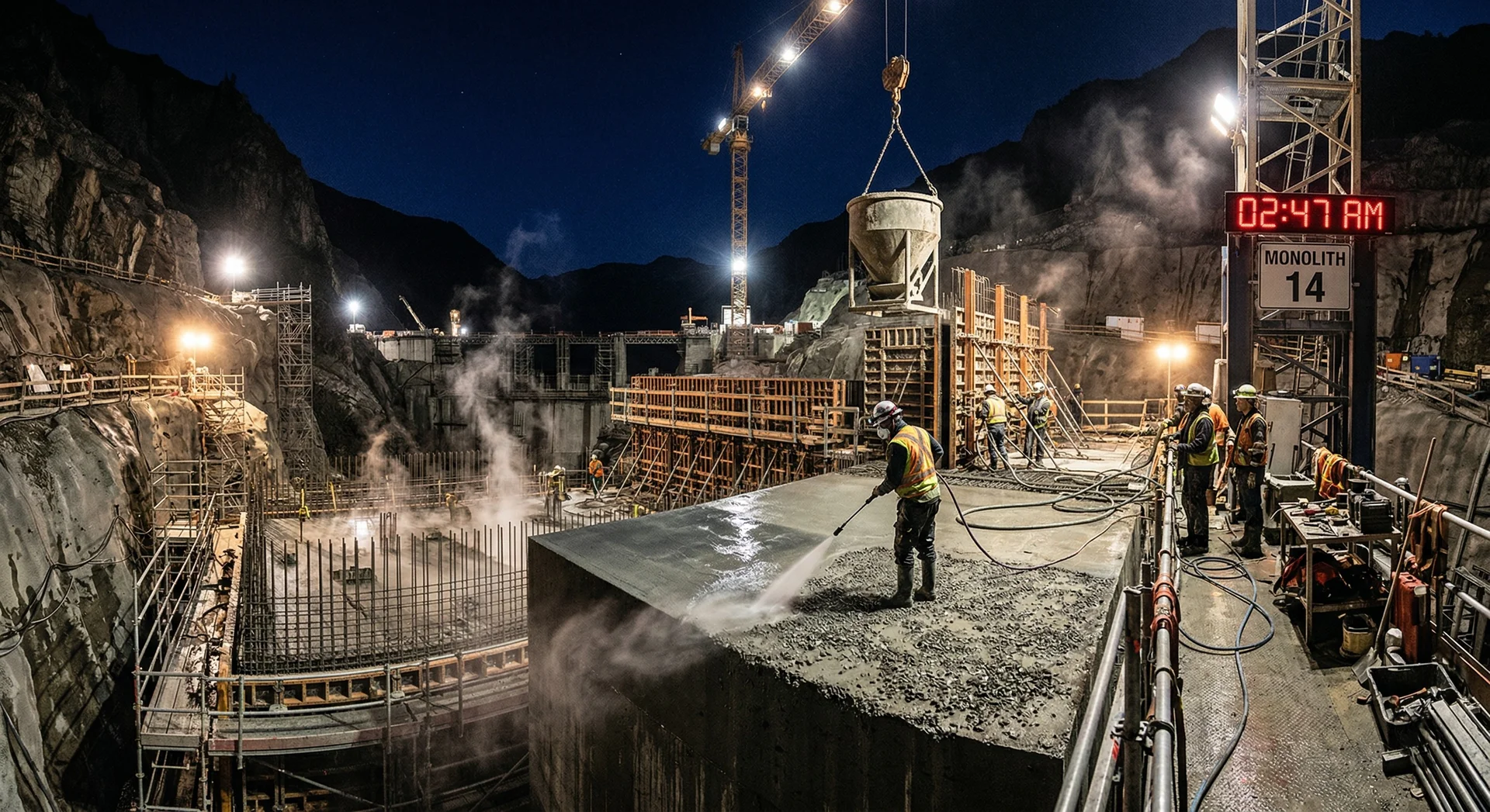
Heat of hydration in thick sections. Invert concrete in large tunnels can reach 1 to 2 metres thick at the springline. This is mass concrete, and it needs the full thermal control treatment we describe in our thermal control article.
Placement methods and their failure modes
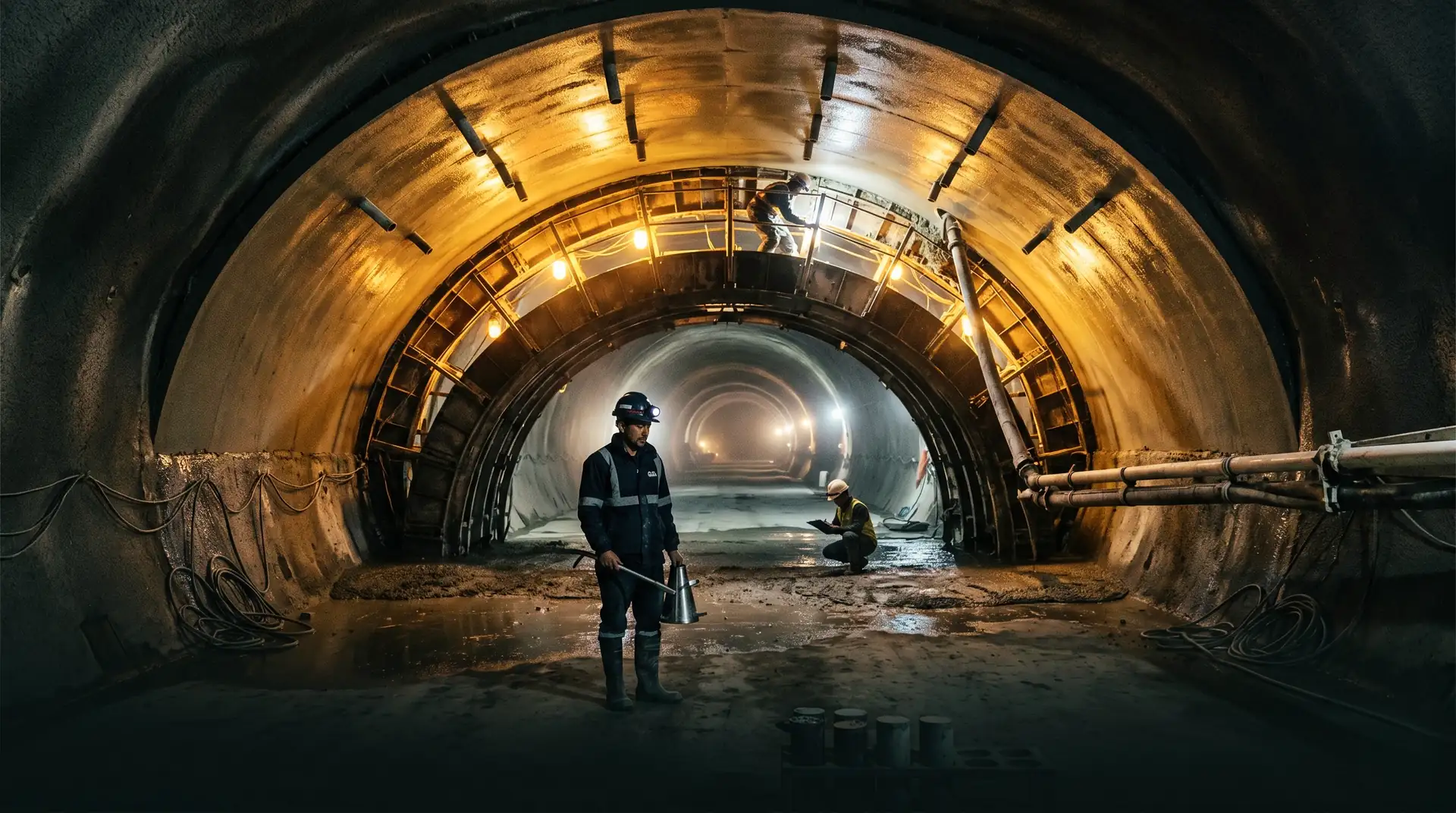
Headrace tunnel concrete is placed against curved formwork, often inverted, in long uninterrupted drives that may extend hundreds of metres. The placement geometry creates failure modes that surface concrete placements never see.
Crown voids and honeycombing
The most common defect. Concrete placed at the crown of a tunnel arch must travel laterally through the formwork, often more than 5 metres, and consolidate against the rock surface. Air pockets and honeycomb zones form when the placement rate is too high, when consolidation is inadequate, or when pumped concrete loses workability before reaching the crown.
Prevention: contact grouting through pre-installed grout pipes after the concrete cures. This is not optional in Indian practice; IS 5878 Part 6 requires it. The grouting fills voids and bonds the lining to the rock, restoring the structural and hydraulic integrity of the contact zone.
Cold joints between pours
Long tunnel drives are placed in segments, typically 9 to 12 metres long. The joint between successive segments is a cold joint, and unless it is treated correctly, it will leak.
Prevention: surface preparation (high-pressure water blasting or hand chipping to expose aggregate), bedding mortar or epoxy bond coat at the joint, and reinforcement continuity across the joint. The joint detail matters as much as the concrete itself.
Thermal cracking in thick inverts
Where the tunnel invert is several metres thick (large tunnels, near surge shafts, at junctions), heat of hydration generates the same temperature differentials we see in dam mass concrete. The thermal cracking section of our thermal control article applies in full.
Chemical attack from project water
Water in the tunnel during operation is reservoir water, not aggressive. But during construction and dewatering, the lining is exposed to groundwater seepage, which can be sulphate-rich, chloride-rich, or acidic. The exposure is often more aggressive than the operational exposure. Mix design should target the worst exposure case, not the typical operational case.
Post-construction shrinkage cracks
Concrete shrinks as it dries and cools. In a tunnel lining, the lining-to-rock contact restrains this shrinkage, generating tensile stresses and cracks. These cracks are not always visible, but they show up as seepage rings during the first impoundment.
Prevention: low-shrinkage mix design, controlled curing temperatures, and contact grouting at low pressure to seal the residual cracks before impoundment.
The contact zone matters more than the lining strength
Most headrace tunnel lining failures originate not in the lining itself, but at the contact between lining and rock, or at the joints between successive pours. A perfectly specified M40 mix poured into a poorly consolidated arch with untreated cold joints will leak. A well-placed M30 mix with disciplined joint treatment and contact grouting will not.
Quality control for headrace tunnel concrete
Tunnel concrete is harder to quality-control than surface concrete because the placement is hidden, access is limited, and conditions change rapidly between segments. The QC programme has to be designed for the constraints, not adapted from surface practice.
Pre-pour QC
- Approved mix design with verified trial mixes for each cement-aggregate combination used
- Aggregate moisture monitoring at the batching plant (twice per shift minimum)
- Pre-pour inspection of each segment: formwork alignment, reinforcement cover, embedment fittings, grout pipe layout
- Pre-pour meeting between QC engineer, contractor’s foreman, and tunnel engineer (not optional)
During-pour QC
- Slump test on every truck arrival at the tunnel face
- Concrete temperature recorded at delivery and at placement
- Cube samples cast at frequency specified in IS 456 or project spec, whichever is tighter
- Continuous monitoring of placement rate, vibration coverage, and concrete consolidation at the crown
Post-pour QC
- Cube testing at 7 and 28 days, with 90-day testing for SCM-rich mixes
- Permeability testing per IS 3085 on cores or moulded specimens for pressure sections
- Lining thickness verification by core drilling at specified intervals
- Contact grouting before the next segment is placed
- Joint inspection and sealing where required
Pre-impoundment testing
- Watertightness test on the completed tunnel section before first filling
- Seepage rate measurement at design pressure
- Inspection of any visible defects before they are flooded out of reach
PCCI’s QA/QC service is built around the field reality that tunnel concrete defects are expensive to find after the fact and almost impossible to fix once the tunnel is impounded. The QC programme has to catch issues at placement, not at first filling.
How PCCI approaches headrace tunnel concrete
Headrace tunnels are part of nearly every hydropower project in PCCI’s 4,000+ MW portfolio. The expertise built across Karchham Wangtoo (1,000 MW), Tala (1,020 MW), and Mangdechhu (720 MW) covers the full range of tunnel conditions: weathered Himalayan strata, high-pressure pressure shafts, long drives in competent rock, and the joint geometries unique to underground hydropower works.
Our mix design service addresses the hydraulic, structural, and durability priorities of tunnel concrete in their order of importance. Our troubleshooting service handles the placement defects that show up after the first dewatering, before they become structural problems.
Book a Technical Call → to discuss your project’s headrace tunnel concrete requirements.