The right tool for specific jobs
Self-compacting concrete (SCC) is the answer to placement geometries where vibration is impossible. It flows under its own weight, fills the formwork, and consolidates without external compaction. The technology emerged in Japan in the 1980s and has been refined globally since, with comprehensive specification frameworks from EFNARC (European Federation of National Associations Representing producers and applicators of specialist building products for Concrete) and ACI 237R-07 (Self-Consolidating Concrete).
For most dam concrete, SCC is unnecessary. Mass concrete bodies, RCC lifts, conventional reinforced concrete, and most structural elements are well-served by conventional concrete with proper vibration. The cost premium of SCC, typically 20 to 50 percent on materials, is not justified where conventional concrete works.
For specific applications on hydropower projects, however, SCC is genuinely the right tool. Where conventional placement is impractical and vibration cannot reach the placement zone, SCC is often the only way to achieve the placement quality the design requires. Recognising those applications and specifying SCC correctly is part of modern hydropower concrete engineering.
Where SCC is genuinely useful
Five applications on hydropower projects benefit from SCC.
1. Second-stage powerhouse concrete
Second-stage concrete in turbine pits and powerhouse foundations is placed in confined spaces around dense embedded steel and reinforcement. The placement geometry is often inverted, with concrete needing to flow upward into pockets and recesses before consolidating. Conventional placement with internal vibration is difficult; access is limited, and over-vibration risks displacing the precision-aligned embedded steel.
SCC handles this geometry. The concrete flows around the embedded steel, fills the recesses, and consolidates by gravity. The vibrators that would otherwise contact the embedded steel are not needed.
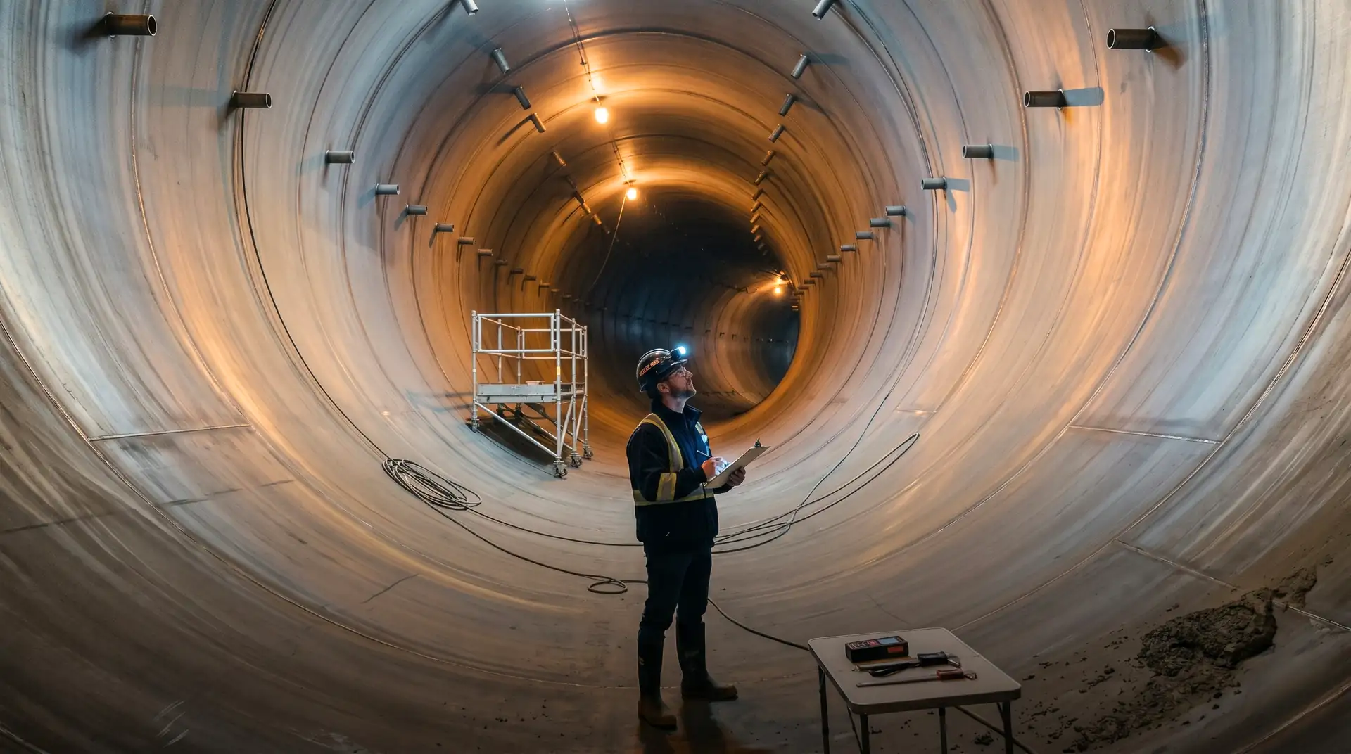
2. Embedded steel liner backing concrete
Concrete behind embedded steel liners in pressure shafts and penstocks is placed in the annular space between the steel liner and the surrounding rock or formwork. The space is typically 200 to 600 mm wide, often inverted at the crown, and difficult to consolidate by vibration without contacting the liner.
SCC fills the annular space without vibration, reducing the risk of crown voids and improving the bond between concrete and liner.
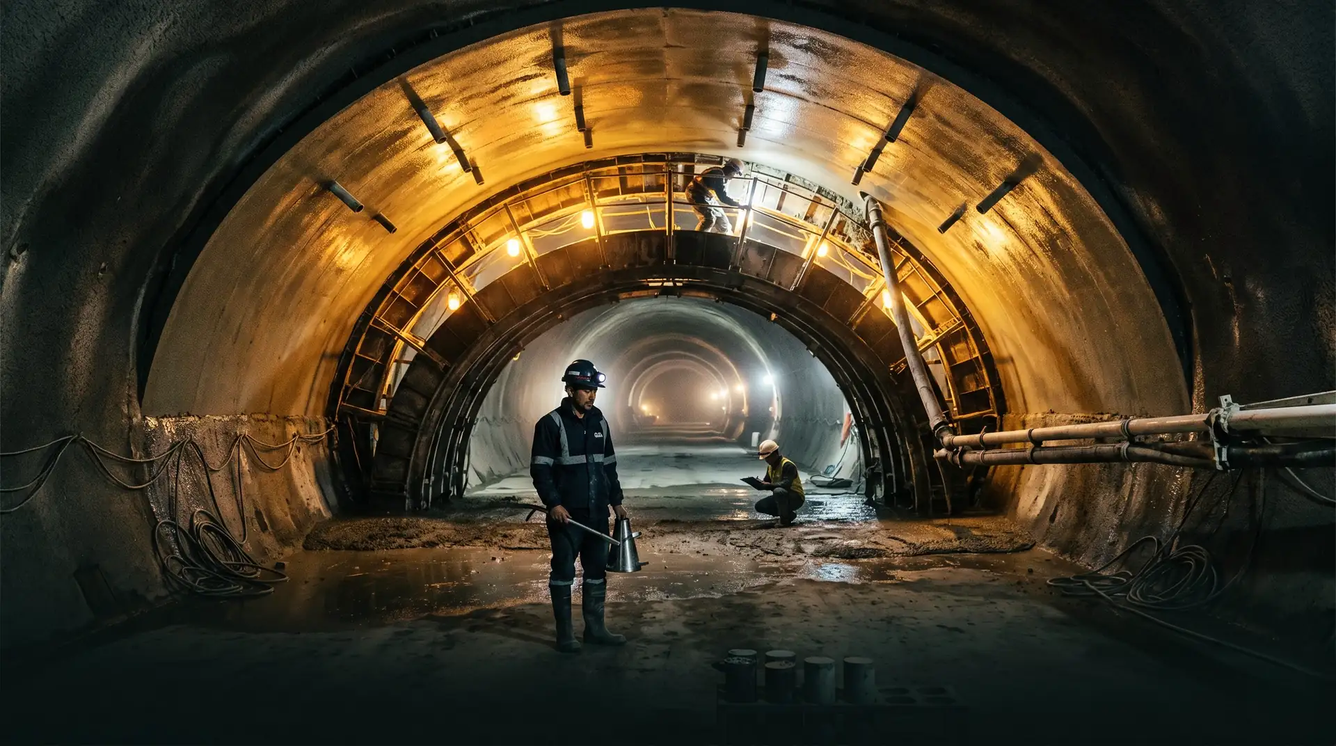
3. Tunnel crown concrete
The crown of a headrace tunnel concrete lining is placed against the rock or formwork at the top of the tunnel, with concrete travelling laterally and upward to fill the space. Conventional consolidation at the crown requires careful vibration timing and placement rate; honeycombing at the crown is one of the most common defects.
SCC at the crown, typically replacing only the last metre or so of placement, eliminates the consolidation issue and produces consistently void-free crown concrete.
4. Congested reinforcement zones
Some structural concrete elements have reinforcement so dense that conventional concrete cannot flow between bars. Examples include seismic-detailed columns, transfer beams, gantry beam connections, and pile cap reinforcement. Conventional placement requires very fluid concrete plus aggressive vibration, which can produce segregation.
SCC flows through congested reinforcement without segregation, and without the vibration that would otherwise be needed.
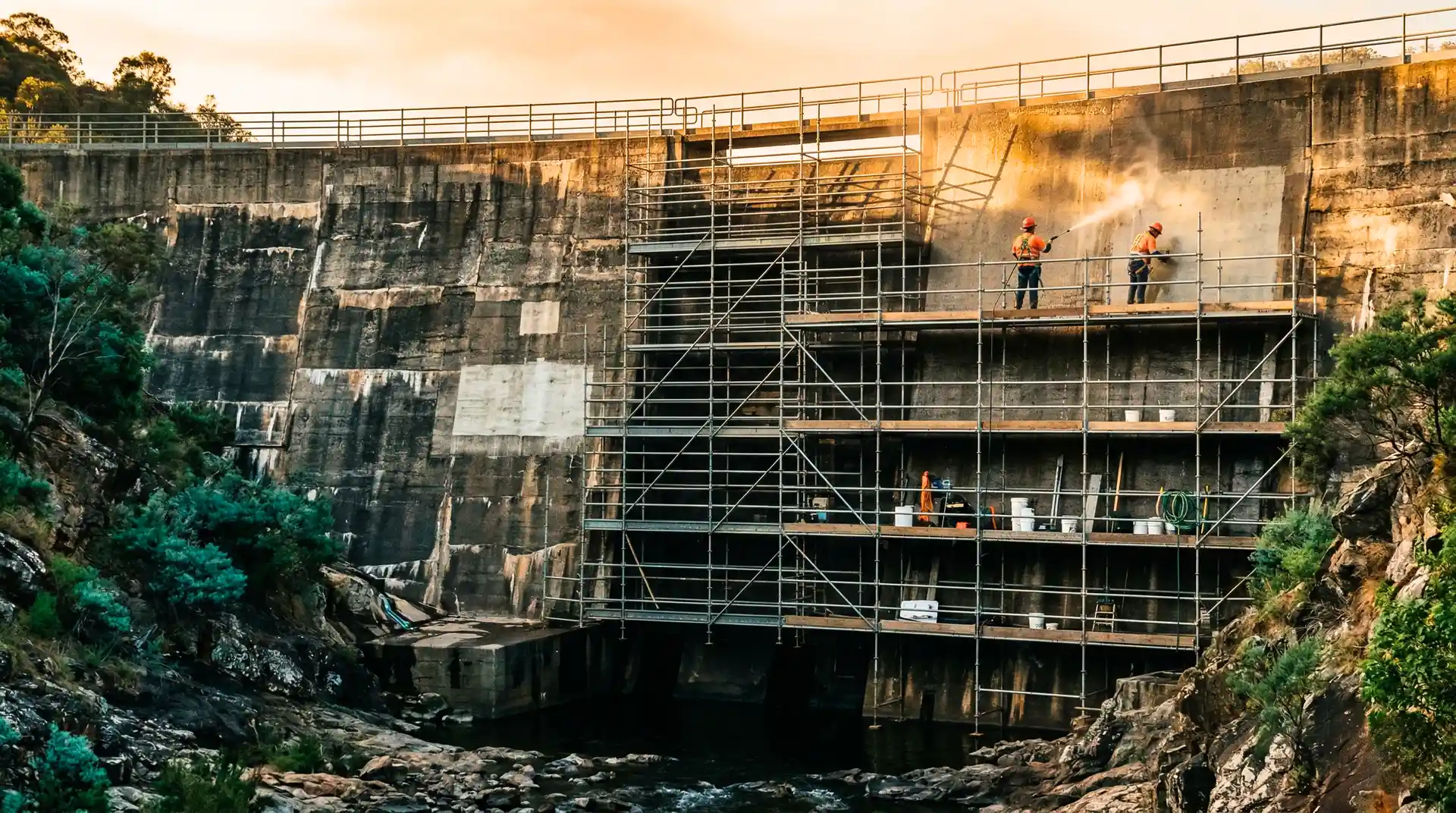
5. Repair concrete in confined zones
Repair concrete for spalled, eroded, or damaged structural concrete is sometimes placed in confined repair zones where conventional placement is impractical. SCC fills the repair geometry without vibration access, producing better repair quality.
For mass concrete dam bodies, RCC, ordinary reinforced concrete walls and slabs, and most routine concrete on the project, SCC is generally unnecessary. The cost premium, the additional QC complexity, and the more demanding mix design discipline are not justified by the benefit.
The EFNARC and ACI 237R specifications
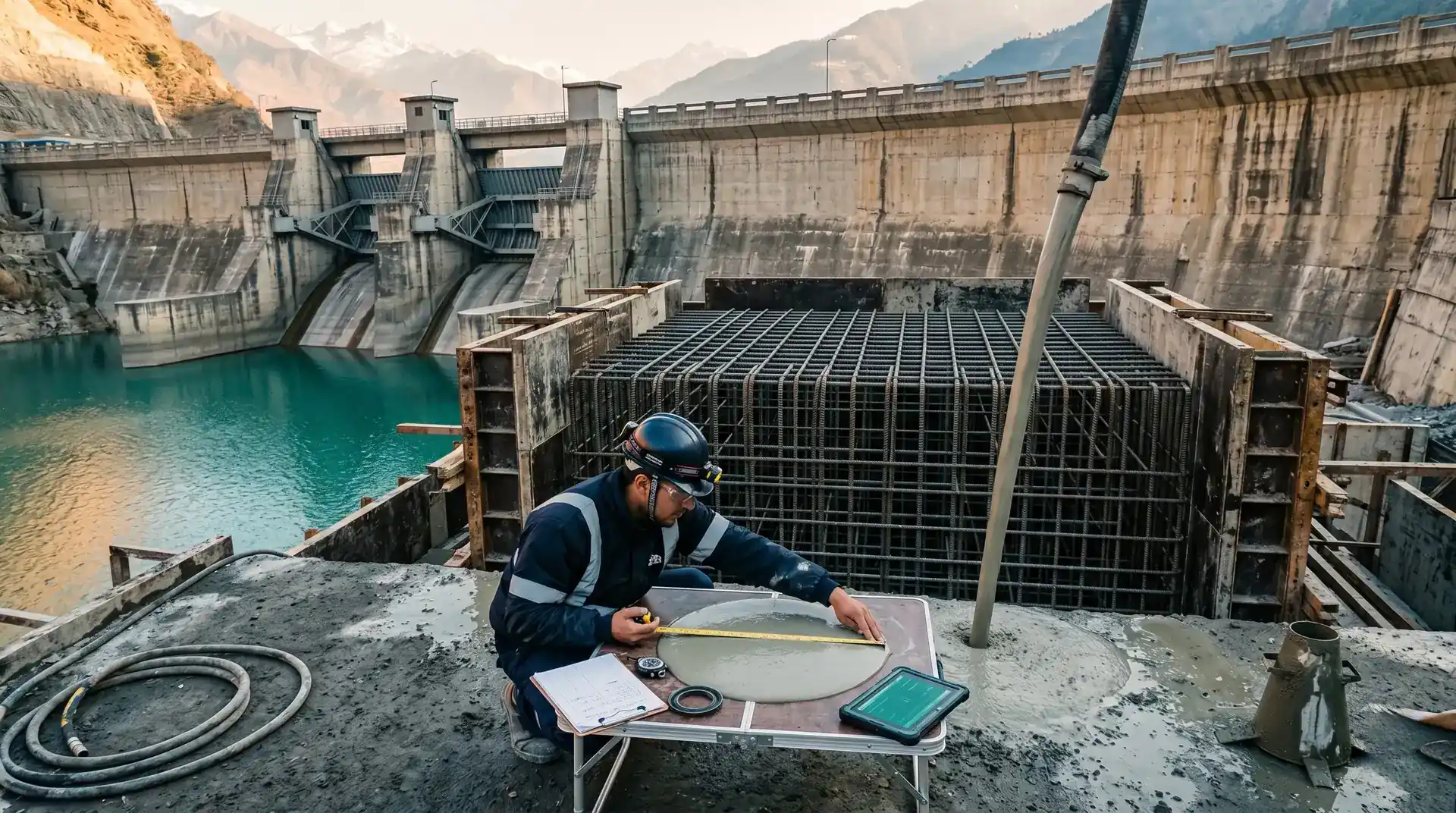
SCC is specified through five concrete properties measured by standard tests.
| Property | Test | Typical SCC range |
|---|---|---|
| Slump flow | EFNARC slump flow test (concrete spread on flat plate) | 600 to 750 mm |
| V-funnel time | EFNARC V-funnel test (time to flow through funnel) | 6 to 12 seconds |
| J-ring | Passing ability through reinforcement bars | Difference < 50 mm |
| L-box | Passing through obstacles into a confined space | H2/H1 ratio > 0.8 |
| Compressive strength | IS 516 or ASTM C39 | Project specification |
Each project specifies the target ranges for these properties based on the placement geometry, reinforcement density, and structural strength requirements. Tighter ranges (slump flow 650 to 700, V-funnel 8 to 10 seconds) for the most challenging placements; broader ranges for simpler applications.
The acceptance test programme is significantly more demanding than for conventional concrete. Where conventional concrete acceptance is based on slump and 28-day cube strength, SCC acceptance requires the full EFNARC suite at every truck arrival, plus cube strength.
SCC needs more QC, not less
The intuition that SCC eliminates labour because vibration is not required is partially correct, but the saved vibration labour is offset by additional QC labour. Each SCC truck arrival requires the EFNARC test suite, which takes more time than slump testing alone. The QC engineer must be more skilled in interpreting SCC behaviour. The net labour cost is roughly similar; what is gained is placement quality in geometries where conventional concrete struggles.
Mix design for hydropower SCC
SCC mix design is more demanding than conventional concrete mix design. Three priorities and five trade-offs.
Priorities
- Flowability measured by slump flow, achieved by high-range water-reducing admixture (HRWR) at adequate dosage.
- Segregation resistance measured by visual stability index and V-funnel time, achieved by viscosity-modifying admixture (VMA) plus higher fines content.
- Passing ability measured by J-ring and L-box, achieved by lower coarse aggregate volume and well-graded fine particles.
Trade-offs
Increasing HRWR dosage improves flowability but worsens segregation. Increasing VMA improves segregation resistance but reduces flowability. Increasing fines content improves passing ability but increases shrinkage and heat of hydration. Reducing coarse aggregate volume improves passing ability but increases cement and admixture cost. Reducing maximum aggregate size improves passing ability but reduces packing efficiency.
The mix design is iterative, with trial mixes adjusting HRWR and VMA dosages until all five EFNARC properties are simultaneously within target. For a hydropower project starting SCC use for the first time, 6 to 12 trial mixes are typical.
Typical proportions for hydropower SCC
For confined placement applications on hydropower projects:
- Cement: 350 to 450 kg/m3 (typically OPC or PPC)
- Fly ash or GGBS: 100 to 200 kg/m3 (25 to 35 percent of total cementitious)
- Total fines (cement + fly ash/GGBS + filler): 500 to 600 kg/m3
- Maximum coarse aggregate size: 10 to 20 mm
- Coarse aggregate volume: 290 to 340 litres/m3
- Fine aggregate volume: balance to total
- Water-cement ratio: 0.40 to 0.45
- HRWR (polycarboxylate ether type): 1.0 to 1.5 percent of cementitious mass
- VMA: 0.05 to 0.20 percent of cementitious mass
These are starting points for trial mix programmes; actual project mixes vary based on aggregates, cement, and ambient conditions.
Placement procedures
SCC placement differs from conventional concrete placement in several ways.
Continuous placement. SCC is placed continuously without interruption. Stopping and restarting can produce cold joints because the leading edge of the placed SCC begins to set while the next batch is delayed.
Lower placement rate. SCC is placed at a slower rate than conventional concrete, typically 10 to 30 m3/h, to allow even flow distribution and avoid pressure surges in the formwork.
Higher form pressure. SCC exerts full hydrostatic pressure on the formwork (because it does not consolidate from vibration). Forms must be designed for full hydrostatic pressure, often two to three times the equivalent conventional concrete pressure for the same placement height.
No vibration. SCC consolidates by gravity. External vibration is not used and can damage the SCC characteristics if applied.
Surface finishing. SCC produces a different surface finish from conventional concrete, often a smoother appearance with less bug-holing if the mix is properly designed.
Specify SCC by application, not by default
The most common error in SCC use on hydropower projects is over-specification: requiring SCC for routine placements where conventional concrete works well. The cost premium and QC complexity are not justified. The right approach is to specify SCC for the specific applications where the placement geometry demands it (second-stage powerhouse, embedded liner, crown concrete, congested reinforcement) and use conventional concrete elsewhere. The same mix design discipline applied to fewer pours produces better outcomes.
How PCCI approaches SCC for dam construction
SCC is part of the mix design portfolio on PCCI’s projects where confined placement applications justify it. The applications across the 4,000+ MW portfolio, particularly Tala (1,020 MW), Mangdechhu (720 MW), and Punatsangchhu-1 (1,200 MW), have included second-stage powerhouse concrete and tunnel crown concrete where SCC was the right tool.
Our QA/QC service covers the EFNARC test suite during SCC placement and the acceptance criteria specific to the SCC application.
Book a Technical Call → to discuss your project’s SCC requirements.