Pre-cooling is the first line of defence against thermal cracking. It reduces the starting temperature. But for thick mass concrete sections in conventional concrete gravity dams, pre-cooling alone is often not enough.
Consider a dam section 15 metres wide. Even with the concrete placed at an ideal 15 degrees C, the adiabatic temperature rise from cement hydration adds 25-35 degrees C to the interior. The peak internal temperature reaches 40-50 degrees C. The surface, exposed to ambient air, may be at 15-25 degrees C. The differential between the core and the surface exceeds 20-25 degrees C, the threshold at which thermal cracking becomes likely.
The surfaces cannot cool the interior faster: heat conduction through concrete is slow (thermal diffusivity approximately 0.003 m2/hour). In a 15-metre section, heat from the centre takes months to reach the surface by conduction alone.
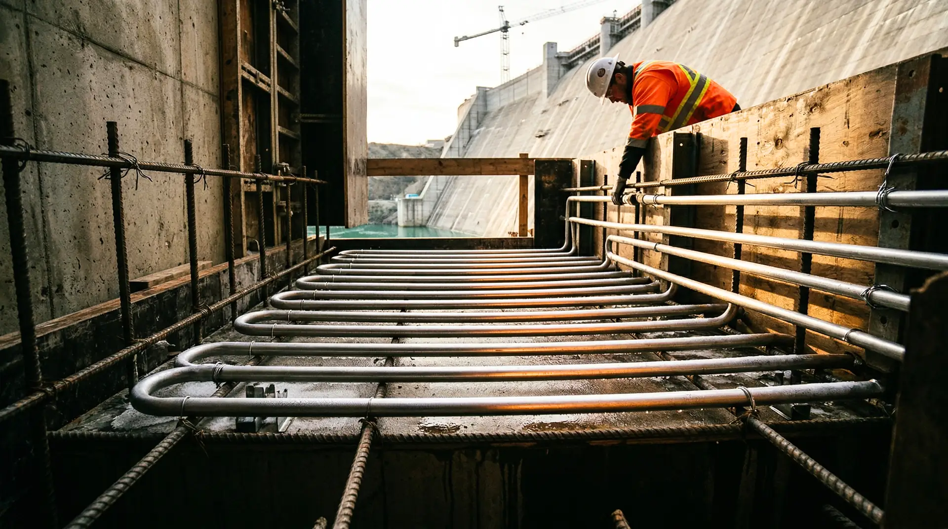
Post-cooling solves this by bringing the cooling medium inside the concrete. Embedded pipes carrying chilled water create internal heat sinks that extract heat from within the mass, reducing both the peak temperature and the thermal gradient.
ACI 207.4R provides the definitive design guidance, while ICOLD Bulletin 159 addresses dam-specific thermal considerations. This article translates that guidance into practical engineering for dam construction.
The Physics of Post-Cooling
Heat Transfer from Concrete to Pipe
The embedded pipe extracts heat from the surrounding concrete through conduction. The rate of heat extraction depends on:
- Temperature difference between the concrete and the cooling water (the driving force)
- Thermal conductivity of the concrete (typically 1.5-2.5 W/m per degree C for mass concrete)
- Pipe spacing (closer pipes extract heat faster but cost more)
- Pipe diameter (larger pipes carry more water but displace more concrete)
- Water flow rate (higher flow maintains a lower outlet temperature, increasing the driving force)
- Cooling water inlet temperature (lower inlet temperature provides a larger temperature difference)
The heat transfer is not instantaneous. The concrete nearest the pipe cools first. The concrete midway between adjacent pipes cools last. This differential cooling creates a temperature gradient around each pipe that generates tensile stress in the concrete between pipes.
The Cooling Rate Limit
This is the critical design constraint: the cooling rate must be slow enough that the temperature gradient around each pipe does not create tensile stresses exceeding the concrete’s tensile capacity.
Maximum recommended cooling rate: 0.5-1.0 degrees C per day (measured as the average temperature drop of the concrete mass per day).
Exceeding this rate risks creating pipe cracks: radial cracks originating at the pipe and extending outward through the concrete. These cracks are particularly insidious because they are internal, invisible from the surface, and create seepage paths within the dam body.
The paradox of post-cooling: it is designed to prevent thermal cracking, but if operated too aggressively, it causes a different type of thermal cracking. The design must balance the benefit (reduced peak temperature and overall gradient) against the risk (local gradient around the pipes).
Pipe System Design
Pipe Material
Thin-wall steel pipe (per BIS IS 1239 for mild steel tubes):
- Typical size: 25 mm (1 inch) nominal diameter, 1.5-2.0 mm wall thickness
- High thermal conductivity: excellent heat transfer from concrete to water
- Traditional choice with extensive track record
- Disadvantages: heavier (more difficult to install), susceptible to corrosion (if water quality is poor), more expensive
HDPE pipe (conforming to ASTM D3350 or equivalent):
- Typical size: 25-32 mm outer diameter
- Lower thermal conductivity than steel (partially offset by thinner walls and flexibility)
- Lightweight, easy to handle and install
- Corrosion-resistant
- Less expensive
- Growing adoption on modern projects
- Disadvantage: more vulnerable to kinking during installation
Pipe Layout
The pipe layout is designed on a grid within each lift:
Horizontal spacing: 1.0-2.0 metres between adjacent pipes within a lift. Tighter spacing provides more uniform cooling. Typical: 1.5 metres.
Vertical spacing: 1.5-3.0 metres between pipe layers (corresponding to 1-2 conventional concrete lift heights). Typical: 1.5 metres (one pipe layer per lift for 1.5 m lifts).
Pipe length per circuit: Each circuit (a continuous run of pipe from inlet to outlet) should be limited to 150-300 metres. Longer circuits lose cooling effectiveness because the water heats up along the pipe length, and the concrete near the outlet receives less cooling than the concrete near the inlet.
Layout pattern: Pipes typically run in a serpentine (back-and-forth) pattern within each lift, with the inlet and outlet on the same face (typically downstream) for access during operation.
Manifold System
The pipe circuits connect to manifolds (headers) that distribute chilled water from the cooling plant and collect the warmed return water:
- Supply manifold: Distributes chilled water at controlled pressure and flow to individual circuits
- Return manifold: Collects return water and routes it back to the chilling plant
- Flow control valves: Individual valves on each circuit to adjust flow rate based on the temperature monitoring data
- Temperature measurement: Inlet and outlet temperature recorded for each circuit (the temperature rise from inlet to outlet indicates the heat extraction rate)
Operating the Cooling System
Phase 1: Initial Cooling (Days 1-21)
Objective: Limit the peak concrete temperature by extracting heat during the period of maximum heat generation (typically days 3-14 after placement).
Water temperature: 5-10 degrees C (as cold as the chilling plant can deliver) Flow rate: Maximum (typically 15-25 litres per minute per circuit) Duration: 7-21 days depending on the section thickness and heat generation rate
During this phase, the temperature monitoring system provides critical feedback:
- Concrete temperature at the pipe should decrease steadily
- Concrete temperature between pipes should peak and begin declining
- The differential between pipe and mid-pipe locations must not exceed the maximum gradient (typically 15-20 degrees C)
If the differential approaches the limit, the cooling must be moderated: increase the water temperature, reduce the flow rate, or both.
Phase 2: Intermediate Cooling (Weeks 3 to Months 3-12)
Objective: Bring the concrete temperature gradually toward its long-term equilibrium temperature (the mean annual ambient temperature at the site).
Water temperature: 10-15 degrees C (slightly warmer than initial cooling) Flow rate: Reduced (10-15 litres per minute per circuit) Duration: 3-12 months depending on the target equilibrium temperature and the section thickness
During this phase, the cooling rate must be carefully controlled:
- Maximum 0.5 degrees C per day average temperature decrease
- The cooling water temperature can be gradually increased as the concrete cools, maintaining a moderate driving force without creating excessive gradients
Phase 3: Final Cooling (Months 6-18, for arch dams with joint grouting)
For arch dams where contraction joints must be grouted to create monolithic arch action, the concrete must be cooled to a temperature below the long-term equilibrium temperature before grouting. This ensures that the concrete will expand slightly after grouting, compressing the grouted joints and maintaining arch action.
Water temperature: As low as possible (5-8 degrees C) Flow rate: Moderate Duration: Until the concrete reaches the target grouting temperature (typically 5-10 degrees C below mean annual temperature) Purpose: Create a controlled contraction that opens the contraction joints, allowing grout to fill them completely
For gravity dams, Phase 3 is not required because gravity dams do not rely on arch action and do not have grouted contraction joints.
Pipe Grouting After Cooling
After cooling operations are complete, the pipes are grouted with cement grout to fill the void. Ungrouted pipes create linear voids through the dam body that act as seepage paths and stress concentrators.
Grouting procedure:
- Flush the pipe circuit with clean water to remove sediment and scale
- Inject cement grout (w:c ratio 0.5-0.7) from one end of the circuit under low pressure (1-3 bar)
- Continue until grout emerges from the other end, confirming full filling
- Allow the grout to set and cure
Thermal Modelling for Post-Cooling Design
The pipe layout, flow rate, water temperature, and cooling schedule are all determined by finite element thermal analysis before construction begins.
Model Inputs
- Concrete thermal properties: Conductivity, specific heat, diffusivity (from laboratory testing of the project mix)
- Adiabatic temperature rise curve: The heat generation profile of the specific cementitious system (from adiabatic calorimetry)
- Boundary conditions: Ambient temperature (daily and seasonal variation), solar radiation, wind, formwork insulation value
- Pipe properties: Diameter, spacing, material, wall thickness
- Cooling water properties: Inlet temperature, flow rate, and their variation over time
Model Outputs
- Temperature distribution at every point in the section at every time step
- Peak temperature at the centre of the section (must not exceed the specification limit)
- Temperature differential between core and surface (must not exceed the cracking threshold)
- Temperature differential between pipe and mid-pipe locations (must not exceed the local cracking threshold)
- Thermal stress field (tensile stresses compared to the concrete’s tensile capacity at each age)
Design Iteration
The pipe layout and cooling schedule are iterated in the model until:
- Peak temperature meets the specification
- All thermal gradients are within safe limits
- Cooling rate does not exceed 0.5-1.0 degrees C per day
- The cooling duration is practical for the construction schedule
When Post-Cooling Is Not Needed
Post-cooling is expensive and complex. It is not needed in every dam:
RCC dams: The thin 300 mm lifts with lower cement content (100-150 kg/m3) have a high surface-to-volume ratio that allows heat to dissipate naturally. Most RCC dams do not require embedded pipe cooling, which is one of their cost and schedule advantages over conventional concrete dams.
Thin sections: Dam sections less than 2-3 metres thick can usually be managed with pre-cooling alone, because the heat path to the surface is short enough for natural dissipation.
Low-heat mixes: Concrete with 40%+ fly ash and total cementitious content below 180 kg/m3 generates low enough heat that peak temperatures stay within limits even in moderate-thickness sections, provided pre-cooling achieves the target placing temperature.
Cost and Complexity
Installation Cost
Pipe material and installation typically costs Rs 200-500 per linear metre of pipe. For a medium gravity dam with 50,000-100,000 metres of embedded pipe, the pipe cost alone is Rs 1-5 crore.
Operating Cost
The cooling plant (water chiller) sized for a medium dam project (500-1,000 m3/day concrete production) costs Rs 3-8 crore installed. Operating power consumption: 100-300 kW continuous during active cooling. Water circulation pumps: 20-50 kW.
Total Post-Cooling System Cost
For a medium conventional concrete gravity dam: Rs 5-15 crore (equipment, pipe, installation, operation). This represents approximately 2-5% of the total concrete cost.
The Justification
The thermal cracking that post-cooling prevents, and the remediation that would be required if cracks form, typically costs 5-20 times the post-cooling system investment. A single major thermal crack requiring investigation, analysis, and grouting can cost Rs 25-50 lakh. A comprehensive thermal cracking remediation programme can exceed Rs 1-5 crore.
The post-cooling system pays for itself by preventing the first significant thermal crack.
Key Principles
-
Design the cooling system with the thermal model, not from rules of thumb. Every dam section has unique geometry, boundary conditions, and concrete properties. The pipe layout and cooling schedule must be specific to the project.
-
Never cool faster than 0.5-1.0 degrees C per day. The purpose of post-cooling is to prevent thermal cracking. Aggressive cooling causes thermal cracking. The cure becomes the disease.
-
Monitor temperatures in real time. Embedded thermocouples between and adjacent to cooling pipes provide the feedback needed to adjust cooling operations. A robust QA/QC system ensures monitoring data is recorded and acted upon. Without monitoring, the operator is cooling blind.
-
Control each circuit independently. Different areas of the dam have different cooling needs. Individual flow control valves on each circuit allow targeted cooling based on the monitored temperatures.
-
Grout the pipes when done. Ungrouted pipes are linear voids through the dam body. They become seepage paths, stress concentrators, and potential corrosion sources. Grouting after cooling is complete is not optional.
-
Integrate post-cooling with pre-cooling and placement scheduling. Post-cooling is one element of the thermal control system. It works with pre-cooling (to reduce the starting temperature) and placement scheduling (to control the timing of heat generation). Optimising one element in isolation sub-optimises the system.
Post-cooling is the most invasive thermal control measure: it requires installing a permanent system of pipes inside the structure, operating it for months to years, and then grouting it. But for thick conventional concrete dam sections where the alternative is thermal cracking, it is also the most effective. The investment in a properly designed and operated post-cooling system protects the dam’s structural integrity for its entire 100-year service life.