Two methods, two concrete philosophies
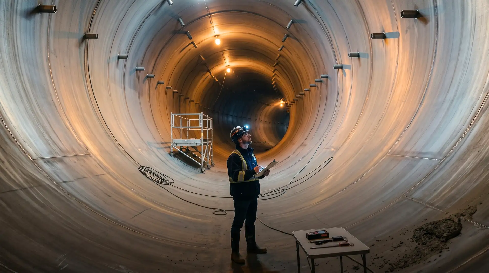
A hydropower headrace tunnel built by NATM and an identical tunnel built by TBM look similar on completion. Both have a smooth concrete inner surface, both convey water, both perform structurally for the project life. The concrete that lines them, however, comes from completely different specifications, was placed by completely different methods, and ages along completely different paths.
NATM concrete is a hand-built product. It is sprayed onto rock by skilled nozzle operators, cast in place against curved formwork by tunnel concrete crews, and shaped to fit whatever rock geometry the excavation has produced. Each lining ring is unique; each placement is conditional on what the previous one revealed.
TBM concrete is a manufactured product. Segments are cast in factory-grade moulds, cured in temperature-controlled chambers, transported to the tunnel face by rail, and erected inside the shield by hydraulic manipulators. Each segment is identical; each ring is geometrically the same as the last.
The right choice between NATM and TBM for a hydropower tunnel depends on the specifics of geology, length, and schedule. The right choice between NATM concrete and TBM concrete depends on what the tunnel is being asked to do for the next 100 years.
NATM concrete: shotcrete primary, cast-in-place secondary
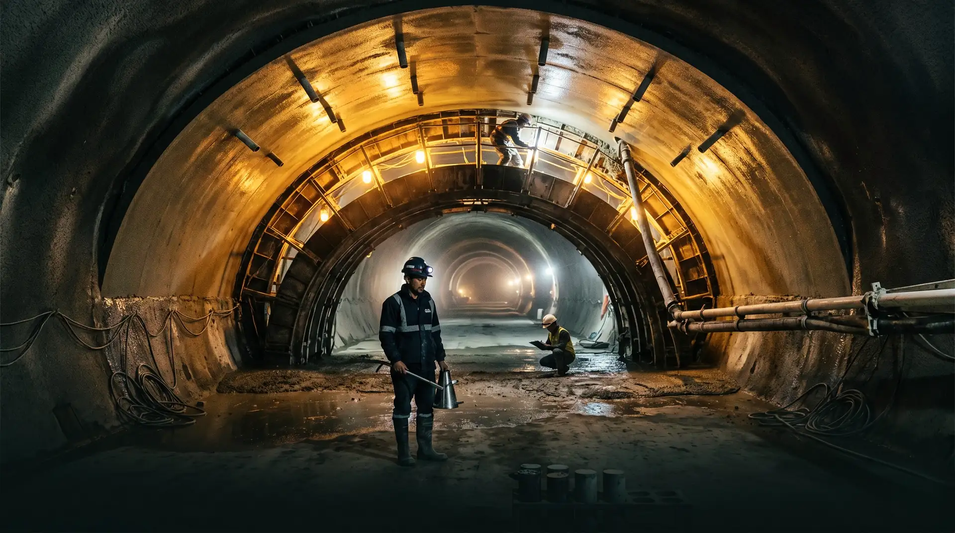
NATM (New Austrian Tunneling Method) uses an observational approach: the rock mass is allowed to deform in a controlled way after excavation, and primary support is sized to allow that deformation while maintaining stability. The primary support is typically shotcrete combined with rock bolts and, in poor rock, lattice girders or steel ribs.
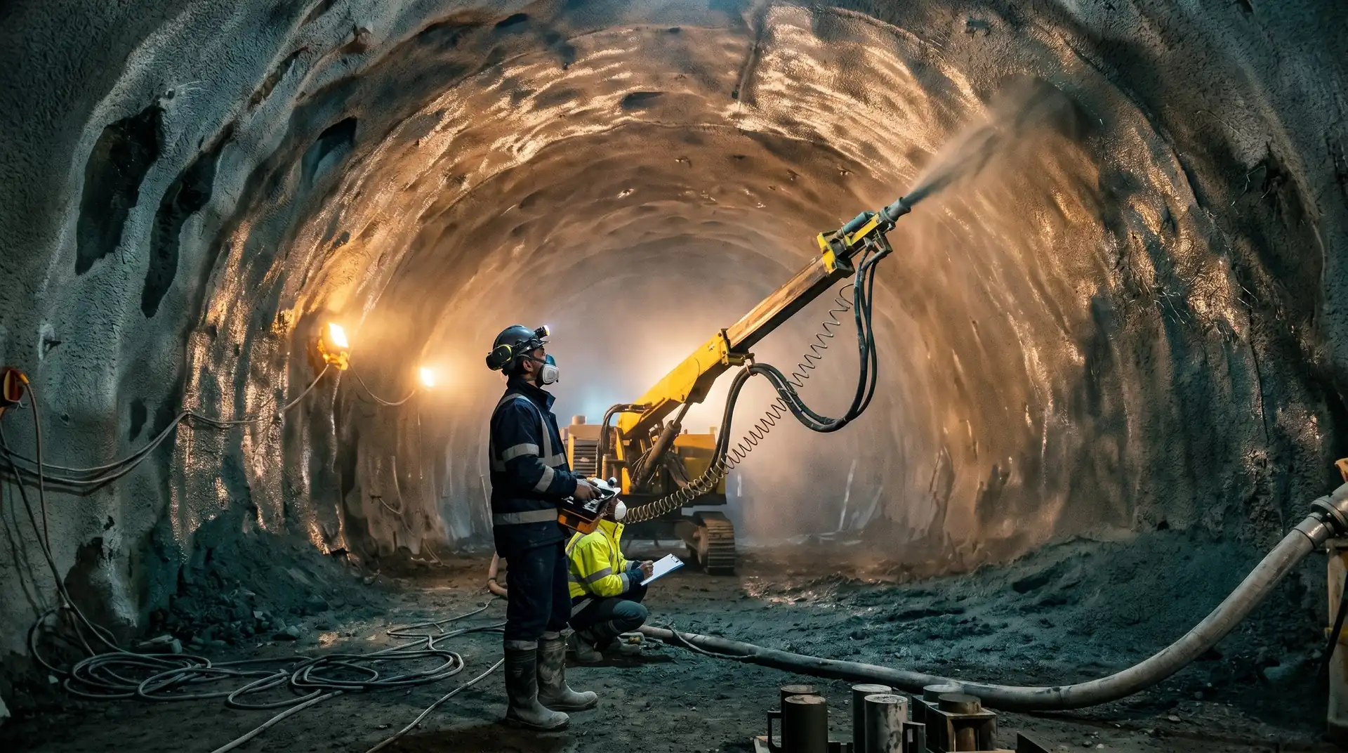
Primary support shotcrete is sprayed onto the rock as soon as practicable after excavation, often within hours. The shotcrete properties:
- Compressive strength typically M30 to M40 at 28 days
- Early-age strength: 0.5 to 1.0 MPa at 1 hour, 5 to 10 MPa at 24 hours (per ITA recommendations and ACI 506R-16 Guide to Shotcrete)
- Reinforcement by steel mesh, steel fibres (40 to 60 kg/m3), or polymer fibres
- Thickness of 50 to 200 mm depending on rock class
- Setting accelerator dosage tuned to ambient and rock temperature
- Application by wet-mix or dry-mix process; wet-mix is now standard for reasons of uniformity and rebound control
Secondary cast-in-place lining is installed after the rock-support system has stabilised, often months after excavation. It serves as the permanent water-bearing structure:
- Compressive strength M30 to M50 depending on internal water pressure
- Cast against curved formwork in segments of 9 to 15 metres
- Reinforced where pressure or rock conditions demand
- Connected to primary support by drainage and waterproofing layers
- Subject to all the placement defects covered in our headrace tunnel article
The two-stage NATM concrete system has one significant advantage: the secondary lining sees only its design load, because the rock-support interaction has already settled by the time it is placed. It also has one significant disadvantage: the interface between primary shotcrete and secondary lining is a potential delamination plane that can cause problems if drainage between them is inadequate.
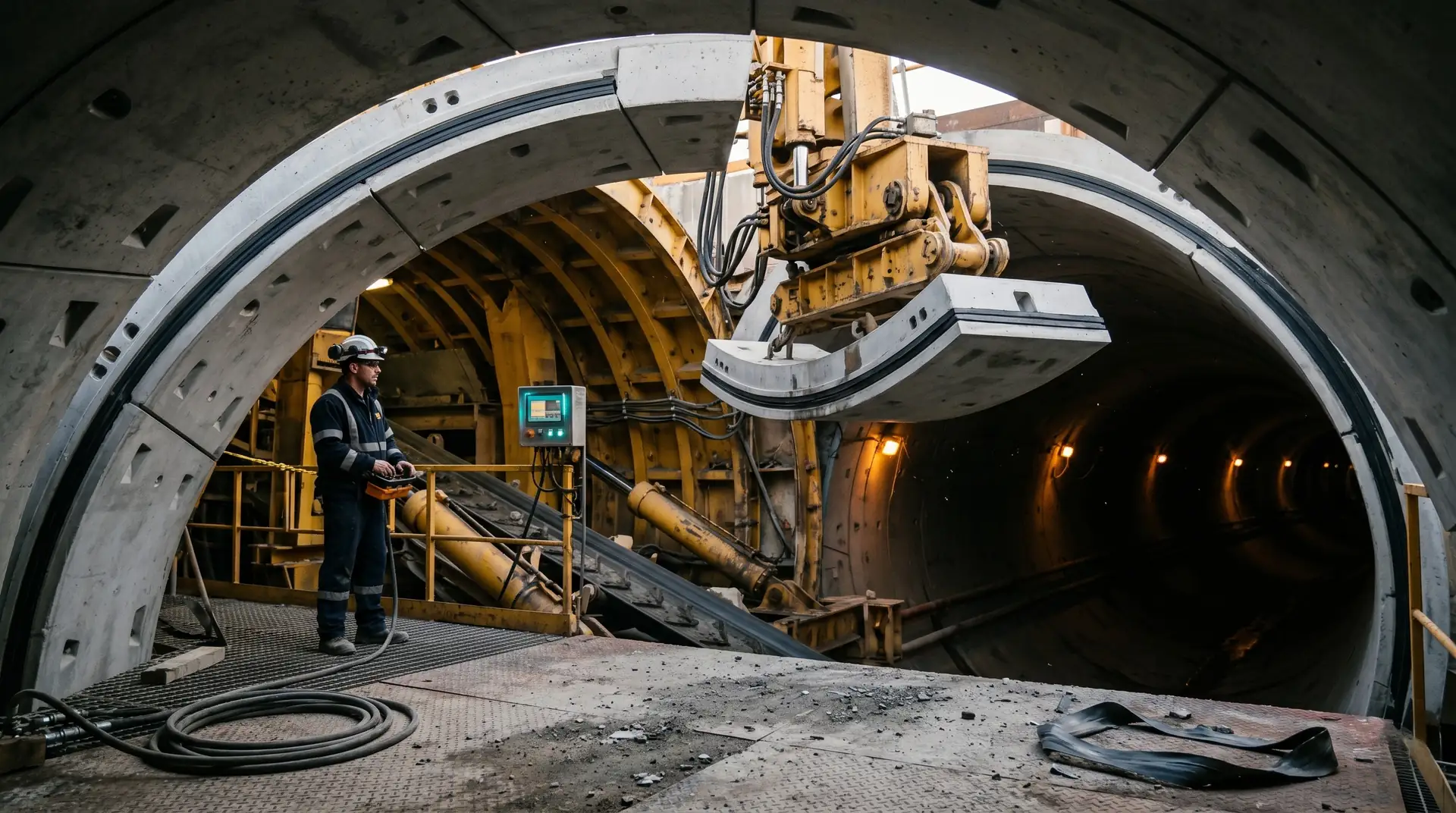
TBM concrete: precast segments, factory-grade quality
TBM tunneling uses a rotating cutter head behind a steel shield. As the cutter excavates, hydraulic jacks push the shield forward, and precast concrete segments are erected inside the tail of the shield to form the permanent lining. The segments interlock at circumferential and longitudinal joints, with EPDM gaskets providing watertightness at every joint.
Segment design parameters:
- Concrete grade typically M50 to M70 (high strength for handling, jacking, and long-term durability)
- Steel reinforcement (single or double layer) or steel fibre reinforcement
- Width: typically 1.4 to 2.0 metres per ring
- Thickness: typically 250 to 400 mm depending on tunnel diameter and rock loads
- Number of segments per ring: typically 5 to 8 plus a key segment
- Connection between rings: bolted or doweled at longitudinal joints, gasketted at circumferential joints
- Lifting features (bolts, sockets, threaded inserts) cast into each segment
Manufacturing tolerances:
- Segment thickness: ±2 mm (much tighter than cast-in-place concrete)
- Joint surface flatness: ±0.5 mm (critical for gasket sealing)
- Gasket groove geometry: ±0.5 mm (critical for gasket performance)
The tight tolerances are achievable only because segments are factory-cast in steel moulds with controlled curing. Field-cast segments would not meet these tolerances and would compromise the gasket sealing system.
TBM segment concrete is engineered for handling, not just service
A TBM segment concrete mix is designed for at least four load cases: factory mould stripping (early-age strength), handling and transport (24-hour strength), erection and jacking (peak compressive strength against the tunnel face), and long-term service. Each load case has its own concrete strength and durability requirement. The mix is optimised for the most demanding case, often the jacking load, which can produce localised stresses far higher than the long-term water-pressure design case.
How rock conditions drive the choice
The single biggest driver of the NATM-versus-TBM decision in Indian and Bhutanese hydropower is rock variability.
TBM works well when rock is:
- Reasonably uniform across the tunnel length
- Not prone to extreme squeezing or swelling behaviour
- Not heavily faulted at unpredictable locations
- Not subject to mixed-face conditions (different rock types within one cutter head sweep)
TBM struggles when rock is:
- Highly fractured or sheared, leading to face collapse and machine entrapment
- Encountering large unmapped fault zones with high water inflow
- Squeezing significantly, leading to shield jamming
- Mixed face (very hard rock alongside very soft material), which damages cutters
NATM works well when rock is:
- Variable and requires support adjustment based on observed conditions
- Prone to fault zones that need pre-investigation and special support
- In areas where contour or alignment changes mid-construction
- In short-to-medium tunnels where TBM mobilisation cost is not justified
The Himalayan geology that hosts most Indian and Bhutanese hydropower projects, with its rapid changes in rock type, weathering depth, and groundwater conditions, has historically favoured NATM. Recent projects have begun using TBM for long, single-formation drives, but most still default to NATM for the headrace and pressure tunnels.
Comparison: concrete specifications side by side
| Parameter | NATM secondary lining | TBM segmental lining |
|---|---|---|
| Concrete grade | M30 to M50 | M50 to M70 |
| Reinforcement | Conventional rebar, project-specific | Conventional rebar, steel fibres, or hybrid |
| Manufacturing | Cast in place against formwork | Precast in factory moulds |
| Thickness | 250 to 500 mm | 250 to 400 mm |
| Tolerances | Conventional cast-in-place | Tight (±2 mm) |
| Watertightness | Cast-in-place joints, waterstops, geomembrane (where used) | EPDM gaskets at every segment joint |
| Repair access | Possible from inside the tunnel | Limited; gasket repair very difficult |
| Vulnerable defects | Crown honeycombing, cold joints, shrinkage cracks | Segment damage during handling, gasket installation errors, ring misalignment |
Watertightness: two different philosophies
NATM watertightness depends on the cast-in-place lining behaving as a continuous, low-permeability membrane. Where the lining cracks or develops cold joint leakage, water enters the tunnel from the rock or, more rarely, escapes from the tunnel into the rock during high-pressure operation. Repairs are typically by injection grouting from inside the tunnel during dewatering.
TBM watertightness is provided by the EPDM gasket system at segment joints. Each circumferential joint has a continuous gasket compressed between adjacent rings. Each longitudinal joint within a ring has a similar gasket between adjacent segments. The concrete itself need not be perfectly watertight; the gasket system handles the water.
EPDM gasket performance over time is well-studied for water and wastewater tunnels, with documented service lives of 50 to 100 years under typical conditions. Hydropower TBM tunnels are a younger application, but the gasket performance principles are the same. Gasket failure is rare when the gaskets are correctly specified, installed, and not damaged during segment handling.
The mechanism that causes most TBM gasket leaks is not gasket aging; it is gasket pinching during installation. A pinched or twisted gasket creates a leak path from day one of operation. The QC programme for TBM lining installation must include systematic gasket inspection at every segment, before the next ring is erected.
NATM defects are repairable; TBM defects are usually permanent
An NATM tunnel with a leaking cold joint or shrinkage crack can be injected with epoxy or polyurethane grout from inside the tunnel during dewatering. A TBM tunnel with a pinched gasket cannot be reached without replacing the segment, which requires opening the surrounding rings and is rarely done. The QC programme for TBM lining installation must catch defects in real time, not at first impoundment.
Quality control: what to watch in each method
For NATM the QC priorities are:
- Shotcrete mix design verified by trial panels and core testing
- Shotcrete thickness verification by depth probes and cores at specified intervals
- Steel fibre or mesh placement check before each spray cycle
- Secondary lining mix design, placement temperature, slump, and consolidation per IS 5878 Part 5 (Concrete Lining for Tunnels)
- Cold joint surface preparation and bond coat application
- Contact grouting after secondary lining cure
- Watertightness test before impoundment
For TBM the QC priorities are:
- Factory QC of segments (concrete strength, dimensions, gasket groove geometry, lifting hardware)
- Segment handling damage inspection at the tunnel face
- Gasket installation visual check at every segment, every ring
- Ring geometry verification (taper, alignment, joint offset) by survey
- Backfill grouting behind segments to fill the annulus between segment outer face and rock
- Watertightness test before impoundment
The QC programmes are different in detail but share the same logic: catch defects before they are buried, because once buried, they are very hard to fix.
How PCCI approaches NATM and TBM concrete
NATM has been the dominant tunneling method on the headrace, pressure, and tailrace tunnels of PCCI’s 4,000+ MW portfolio. Our experience covers shotcrete mix design optimisation, secondary lining QC, and post-construction injection grouting on operating projects. TBM has been used on selected drives in recent projects, and the QC framework for TBM segments is part of our QA/QC service for projects that adopt TBM.
Our independent review service is frequently engaged at the front end of major hydropower projects to review the contractor’s tunnel method statement and concrete specifications, before commitment, when the comparison between NATM and TBM is still open.
Book a Technical Call → to discuss your project’s tunnel concrete requirements.