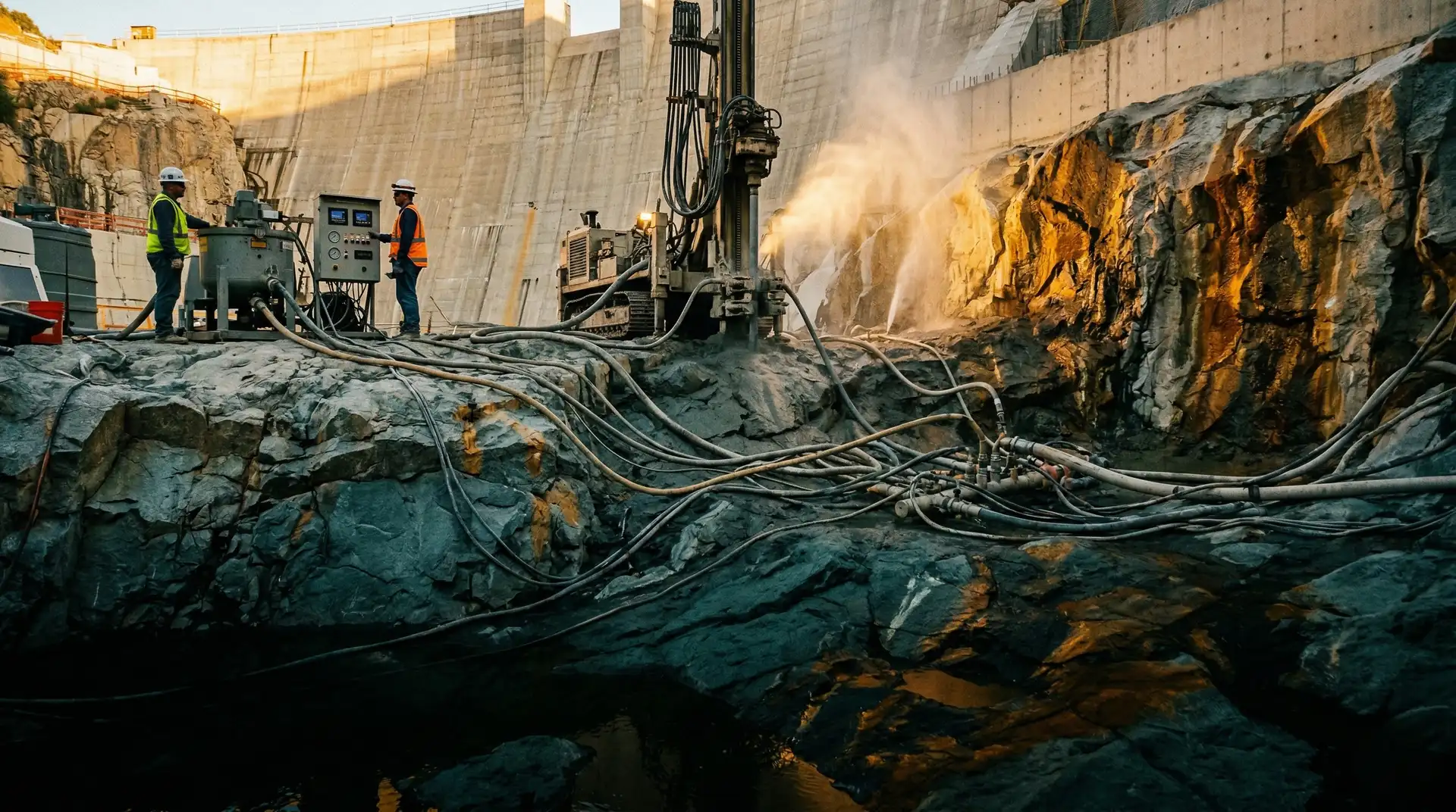
A concrete dam sits on rock. The design assumes that the concrete and rock are in full contact: the dam’s weight transfers uniformly to the foundation, and the concrete-rock interface is watertight enough that the grout curtain and drainage system can control uplift pressures.
In reality, the concrete-rock contact is never perfect. Concrete shrinks as it cures. The underside of the first lift cannot conform to every irregularity in the rock surface. Bleed water collects at the interface, leaving a porous, weak zone. The result is a gap, typically 0.5 to 5 mm, that extends over significant portions of the foundation contact area.
This gap is consequential. It provides a direct pathway for reservoir water to flow beneath the dam, short-circuiting the grout curtain if the gap is continuous across the curtain line. The flowing water creates uplift pressure on the base of the dam, reducing the effective weight that resists sliding. In extreme cases, an ungrouted foundation contact can reduce the dam’s factor of safety against sliding below acceptable limits.
Contact grouting fills this gap. It is the simplest of the three foundation grouting programmes (contact, consolidation, and curtain), but it is not the least important.
Why the Gap Forms
Understanding why the gap forms helps engineers plan when and how to grout it effectively.
Concrete Shrinkage
Concrete shrinks during and after curing through three mechanisms:
Chemical shrinkage. The hydration reaction between cement and water produces hydration products that occupy less volume than the original cement and water. This chemical shrinkage begins immediately and continues for months.
Autogenous shrinkage. In low water-cement ratio concrete (below 0.42), the internal consumption of water by hydration creates internal drying within the paste, causing the concrete to shrink even without external drying. This is significant in the high-quality, low w/c concrete used in the lower lifts of modern dams.
Thermal contraction. The heat of hydration raises the concrete temperature 20 to 40 degrees Celsius above the placement temperature. As the concrete cools back to the ambient rock temperature over weeks to months, it contracts. For a thermal coefficient of expansion of 10 x 10⁻⁶ per degree Celsius and a temperature drop of 30 degrees, the contraction is 300 microstrain, equivalent to 6 mm across a 20-metre block width. Effective thermal control during placement can reduce the peak temperature rise and limit the final gap width, but it cannot eliminate the gap entirely.
The combined effect of these shrinkage mechanisms is a gap at the concrete-rock interface that opens progressively as the concrete ages.
Surface Irregularity
Rock surfaces, even after cleaning and preparation, have ridges, depressions, and undercuts. The fresh concrete cannot fully conform to these irregularities, particularly in undercut areas where gravity prevents the concrete from filling upward-facing voids. These geometric voids are part of the contact gap that grouting must fill.
Bleed Water
Fresh concrete bleeds: water rises through the concrete mass and collects at free surfaces. In the first lift of a dam, the bleed water migrates downward to the concrete-rock contact (since the rock is the lowest free surface), creating a water-filled zone at the interface. When this water eventually dissipates, it leaves a weak, porous layer of high water-cement ratio paste that has poor bond to both the concrete and the rock.
Pre-grouting the foundation rock before concrete placement does not prevent this bleed water accumulation. The bleed water is generated within the concrete itself, and is best controlled through the mix design of the lowest lifts (lower water content, well-graded aggregate, and appropriate use of viscosity modifiers).
Contact Grouting vs. Other Foundation Grouting
The three foundation grouting programmes address different zones and serve different purposes. Confusing them leads to misapplied effort and wasted resources. For a broader overview of how the three programmes fit together, see our companion brief on cement grouting for dam foundations.
| Parameter | Contact Grouting | Consolidation Grouting | Curtain Grouting |
|---|---|---|---|
| Zone treated | Concrete-rock interface (0-5 mm) | Shallow rock (5-15 m depth) | Deep rock (30-100+ m depth) |
| Purpose | Fill gap, ensure load transfer and watertightness at contact | Improve rock strength and stiffness | Create seepage barrier |
| Hole depth | Into concrete, terminating at rock (0.3-1.0 m into rock) | 5-15 m into rock | 30-100+ m into rock |
| Hole diameter | 38-50 mm | 50-75 mm | 50-75 mm |
| Grout pressure | 0.1-0.3 MPa (low) | 0.3-1.0 MPa (moderate) | 0.5-5.0 MPa (high, depth-dependent) |
| Grout mix | Neat cement, w/c 0.6-1.0 | Cement, w/c 0.5-3.0 (variable) | Cement, w/c 0.5-5.0 (variable) |
| Timing | After concrete, 28-90 days | Before or after concrete | Before or after concrete |
| Performed from | Dam gallery | Dam gallery or dam crest | Dam gallery |
| Standard reference | IS 6066:1994 (pressure grouting of rock foundations) | IS 6066:1994 | IS 11293-2 (grout curtains, concrete dams) |
The three programmes are performed in a specific sequence. Curtain grouting is typically performed first (or simultaneously with consolidation grouting) to establish the seepage barrier. Consolidation grouting improves the shallow foundation rock. Contact grouting is performed last, after the concrete has been placed and has completed most of its contraction.
Planning Contact Grouting
Hole Layout
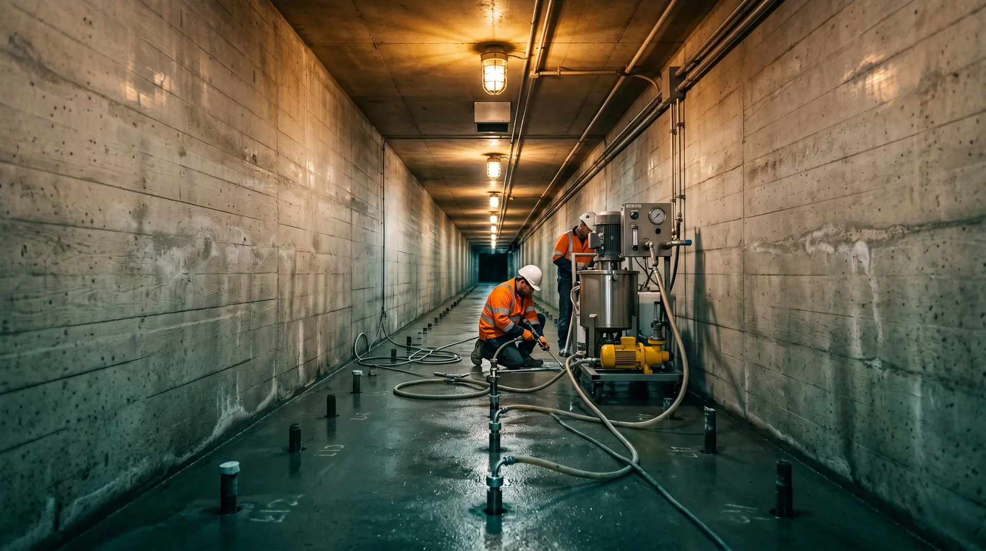
Contact grouting holes are drilled from within the dam’s foundation gallery (or from the dam crest if no gallery exists) through the concrete and into the rock surface. The typical layout:
Spacing: 2 to 3 metres along the gallery axis, with holes angled to intercept the concrete-rock contact at the upstream and downstream faces of the dam block.
Pattern: A single row along the gallery centre line may suffice for narrow dams. For wide dams (base width exceeding 30 metres), two or three rows may be needed: one upstream of the gallery, one downstream, and sometimes one directly beneath the gallery floor.
Depth: The hole penetrates the full thickness of the gallery floor concrete (typically 1 to 2 metres) and extends 0.3 to 1.0 metres into the rock. The hole must clearly pass through the concrete-rock contact zone.
Orientation: Holes are typically vertical or angled at 15 to 30 degrees from vertical to access the contact beneath the gallery walls. The angle ensures that the grout reaches the full width of the contact zone, not just the area directly beneath the hole.
Grout Mix Design
Contact grouting uses relatively simple cement-water grouts. The mix design must balance fluidity (to penetrate the narrow gap) with stability (to prevent settlement and bleeding within the gap).
| Mix Parameter | Typical Range |
|---|---|
| Cement type | OPC or Portland Pozzolana Cement |
| Water-cement ratio (by weight) | 0.6-1.0 (start thin, thicken as needed) |
| Bentonite addition | 0-5% by weight of cement |
| Superplasticiser | 0-1% by weight of cement |
| Mixing method | High-shear colloidal mixer |
| Minimum mixing time | 2 minutes at high shear |
| Marsh cone flow time (target) | 30-45 seconds (quart cone) |
The grout is prepared in a colloidal mixer that operates at 1,500 to 2,000 RPM, fully dispersing the cement particles and producing a stable suspension. Paddle mixers are not acceptable for dam grouting because they produce grout with poor stability and uneven particle distribution.
Per the USBR Design of Small Dams guidance, the starting mix for contact grouting should be a thin, stable grout that can penetrate the narrow gap. If the gap accepts large volumes, the grout is progressively thickened (reduced w/c ratio) to fill the void efficiently. This thin-to-thick progression is also recommended in ICOLD’s bulletins on dam foundations and grouting.
Pressure Limits
Contact grouting pressures must be strictly controlled. The grout is being injected into a thin gap directly beneath the dam concrete. Pressure gauges, flow meters, and the manometer at every header must be calibrated and verified as part of the QA/QC programme for the grouting works. Excessive pressure can:
- Lift the concrete. If the grouting pressure exceeds the weight of concrete above the injection point, the concrete block can be hydraulically jacked upward, opening the contact further and potentially cracking the block.
- Crack the concrete. Young concrete (less than 90 days) has limited tensile strength. Grouting pressure creates tensile stress in the concrete above the injection point.
- Block drains. If grout migrates into the foundation drainage system, it can block drain holes and eliminate the uplift pressure relief that the drainage system provides. This is a particularly serious consequence because blocked drains increase uplift pressures on the dam base.
Typical pressure limits:
| Condition | Maximum Grouting Pressure |
|---|---|
| General rule | 50% of the concrete overburden weight above the injection point |
| Minimum concrete age | 28 days (preferred 60-90 days) |
| Near drain holes | Reduce to 30% of overburden, or grout drains first |
| Near construction joints | Reduce pressure, monitor joints for grout leakage |
| Over unstable rock features | Engineering evaluation required |
For example, if the gallery floor is 3 metres below the dam crest and the concrete has a unit weight of 24 kN/m³, the overburden pressure is 3 x 24 = 72 kPa. The maximum grouting pressure would be 0.5 x 72 = 36 kPa, or approximately 0.036 MPa. This is very low, and it underscores why contact grouting is a low-pressure operation.
On taller dams, where the gallery is deeper within the dam body, the overburden is greater and higher grouting pressures are permissible. But even on large dams, contact grouting pressures rarely exceed 0.3 MPa.
Execution Procedure
Pre-Grouting Preparation
-
Drill holes. Using a percussion or rotary drill, bore through the gallery floor concrete into the rock. Record the depth at which the drill passes from concrete to rock (the concrete-rock contact). Note any voids, soft zones, or water returns during drilling.
-
Wash holes. Flush each hole with clean water to remove drill cuttings and loose material from the contact zone. Record the water return (clear or turbid) and any loss of wash water (indicating permeable zones or voids).
-
Water test. Perform a simple water test at low pressure (0.05 to 0.1 MPa) to assess the permeability of the contact zone. If the hole takes no water, the contact may be tight and grouting may produce negligible takes. If the hole takes significant water, the contact is open and grouting is clearly needed.
-
Install packers. Set a packer at the top of the hole (in the concrete, above the contact) to confine the grout to the contact zone and prevent it from flowing up the hole and flooding the gallery floor.
Grouting Sequence
-
Start with thin grout. Begin injection with a grout mix at w/c 0.8 to 1.0 at low pressure (0.05 to 0.1 MPa). Monitor the grout take (litres per minute) and the pressure.
-
Thicken progressively. If the take is high (indicating a large gap or connected voids), thicken the grout to w/c 0.6 to reduce the volume injected and increase the grout strength. Each thickening step should be recorded.
-
Monitor adjacent holes. Grout appearing at adjacent holes (communication) indicates that the gap is continuous. This is normal and expected. Close the adjacent hole or use it to monitor the spread of grout.
-
Monitor drain holes. If grout appears in any foundation drain hole, stop grouting immediately. The drain hole must be flushed clean and the grouting approach revised (lower pressure, thicker grout, or different hole sequence).
-
Achieve refusal. Continue grouting until the take drops below the refusal criterion (typically less than 0.5 litres per minute sustained for 5 minutes at the specified pressure). Record the total grout volume, the final pressure, and the refusal criterion met.
-
Flush and cap. After refusal, flush the grout line and cap the hole with a mechanical plug or cement mortar.
Record Keeping
Every contact grouting hole must have a complete record:
- Hole number, coordinates, depth, and angle
- Water test results (pressure, flow rate, duration)
- Grout mixes used (w/c ratio, additives)
- Pressure-take-time record (recorded at 1-minute intervals minimum)
- Total grout volume injected (in litres and equivalent bags of cement)
- Communication with adjacent holes or drain holes
- Refusal pressure and criterion
- Any unusual observations (sudden take increases, grout leakage at gallery joints, etc.)
These records are the permanent evidence that the foundation contact has been treated. They are reviewed during dam safety inspections and are essential for evaluating the foundation condition during the dam’s operating life.
Verification
Direct Verification Methods
After contact grouting is complete, the effectiveness of the treatment should be verified.
Water testing of grouted holes. Re-test selected holes (typically 10 to 20% of the total) using the same water test protocol used before grouting. A significant reduction in water take confirms that the contact gap has been filled. If the post-grouting water take is similar to the pre-grouting take, the grouting was ineffective and must be repeated. Decisions on re-grouting, re-drilling, or accepting the treated zone should be supported by an independent technical review on critical projects.
Check holes. Drill additional holes between the grouted holes to verify that the grout has spread to cover the entire contact area. These check holes are water-tested; if they show significant permeability, they are grouted, and additional check holes are drilled to define the boundary of the treated zone.
Core extraction. On critical dam sections, extract cores that pass through the concrete-rock contact to visually verify that grout has filled the gap. The core should show concrete, a grout-filled zone (however thin), and then rock, with no visible voids at the contact.
Indirect Verification
Uplift pressure monitoring. After the reservoir fills, the uplift pressure measured by piezometers in the dam foundation provides indirect evidence of contact grouting effectiveness. If uplift pressures are at or below the design assumptions, the combined effect of the grout curtain, drainage, and contact grouting is performing as intended.
Gallery seepage monitoring. Visual inspection and measurement of seepage in the dam gallery (the amount, location, and character of water entering the gallery through cracks, joints, and weep holes) provides ongoing monitoring of foundation condition. Sudden increases in seepage may indicate deterioration of the contact grout and warrant a focused durability assessment of the dam-foundation interface.
Instrumentation. On modern dams, fibre optic temperature sensing or distributed pore pressure monitoring along the foundation contact can provide continuous data on seepage pathways and the effectiveness of grouting treatment.
Special Considerations
Contact Grouting in RCC Dams
Roller compacted concrete (RCC) dams present particular challenges for contact grouting. The first lift of RCC against the rock foundation is typically a bedding mix (conventional concrete or grout-enriched RCC) intended to fill irregularities in the rock surface. However, the interface between this bedding mix and the rock is still susceptible to gap formation.
RCC dams often do not have a foundation gallery (the RCC placement method makes gallery construction difficult). Contact grouting in these dams may need to be performed from the dam crest through deep holes that penetrate the full height of the dam. This is expensive and difficult to control.
An alternative approach for RCC dams is to use a conventional concrete base slab (1 to 2 metres thick) over the foundation rock, perform contact grouting from within this slab’s construction before RCC placement begins, and then place the RCC on top of the grouted conventional concrete base.
Contact Grouting at Abutments
The dam-abutment contact is as critical as the dam-foundation contact, and often more geometrically complex. The abutment surface may be steeply inclined or irregular, and the concrete-rock gap on a sloping surface can be larger than on a horizontal foundation because gravity pulls the concrete away from the rock.
Contact grouting at abutments requires holes drilled at angles that intercept the sloping concrete-rock contact. The layout may need to be denser (closer spacing) and the verification more intensive because the abutment zone is where water preferentially seeps around the dam.
Timing Relative to Reservoir Filling
Contact grouting must be completed before the reservoir reaches a level where water pressure acts on the foundation. On projects with staged reservoir filling, contact grouting of the lower dam blocks may need to be completed before the reservoir rises to the gallery level.
The project schedule must account for the waiting period between concrete placement and contact grouting readiness (28 to 90 days). On fast-track projects, this waiting period can become a schedule-critical activity. The temptation to grout prematurely must be resisted: grouting before the concrete has completed its thermal contraction results in the grout being cracked by subsequent contraction, leaving the contact ungrouted.
Conclusion
Contact grouting is the final step in establishing a watertight, load-transferring connection between a concrete dam and its foundation rock. It addresses an inevitable physical phenomenon, the gap formed by concrete shrinkage, and converts a potential seepage pathway into a sealed interface.
The principles are straightforward: wait until the concrete has contracted, inject low-pressure grout to fill the gap, control pressures to avoid damaging the concrete or blocking drains, and verify through water testing and check holes that the treatment has been effective.
The execution requires patience (waiting for the right timing), precision (controlling low pressures accurately), and attention to detail (monitoring every hole, recording every observation, checking for grout migration into drains). These are not glamorous skills, but they are essential. A dam with a well-grouted foundation contact starts its operating life with the stability margins that the designer intended. A dam with an ungrouted or poorly grouted contact starts with a hidden deficiency that may take years to manifest but can be difficult and expensive to correct after the reservoir is full. When uplift anomalies or unexplained seepage do appear in operation, structured construction troubleshooting and root-cause analysis is the discipline that converts symptoms into a remediation plan.