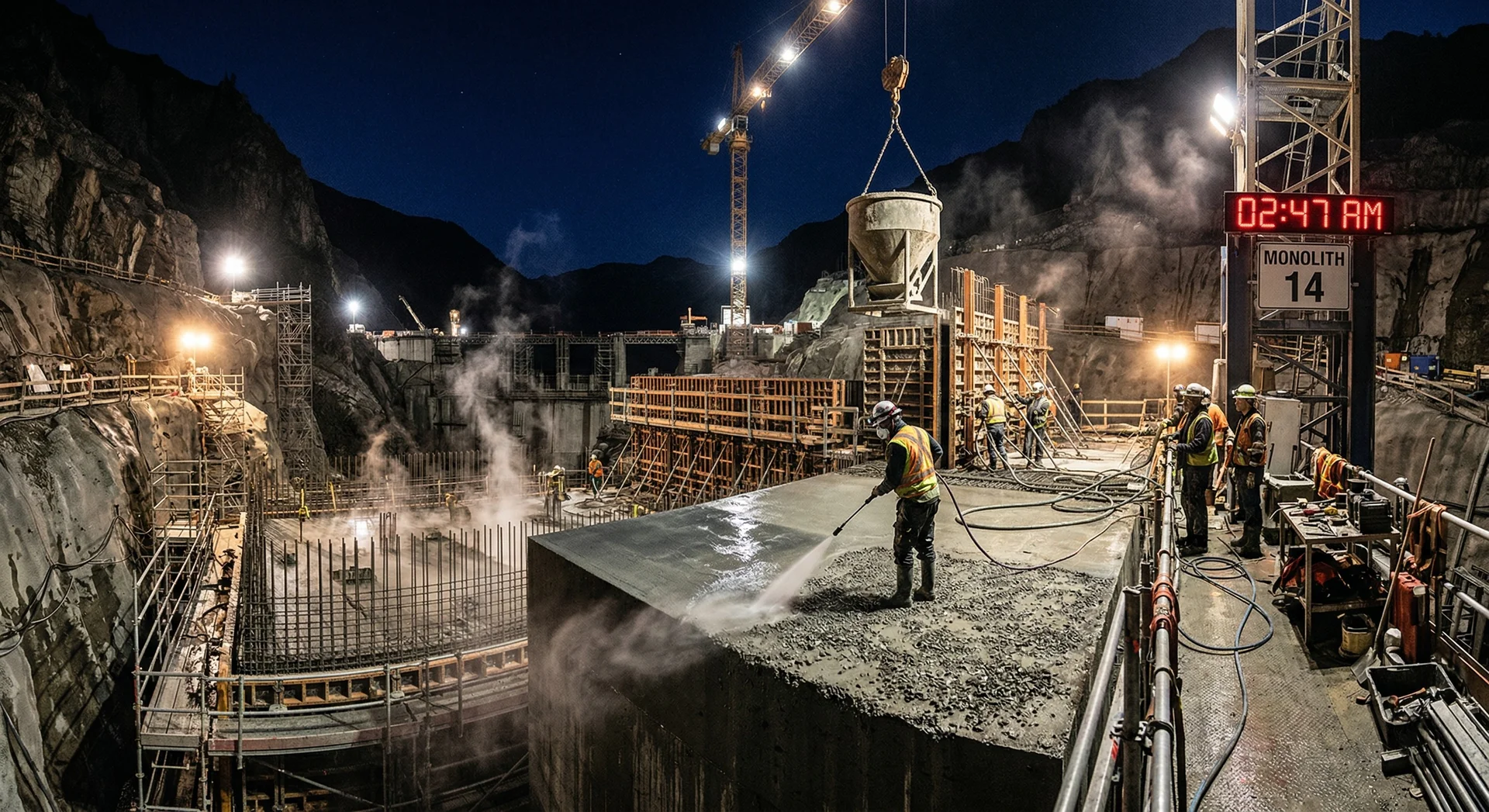
Building a dam is measured in years. The concrete that forms its body must perform for a century. Between the first pour and the last core test lies a continuous chain of quality decisions, hundreds per day, thousands per month, that collectively determine whether the structure will serve its purpose or become a liability.
This guide covers the entire QA/QC process for dam concrete construction: from batching plant commissioning to the 365-day strength test, from the first aggregate stockpile to the final grouting of cooling pipes. It is written for site QC engineers, project managers, and concrete technologists who need a single reference that connects every step in the chain.
The numbers and procedures referenced here are consistent with IS 456, ACI 207 series, IS 14591, IS 457, and ICOLD technical bulletins. Where Indian and international standards differ, both are noted.
Before the first pour: pre-construction QC
The quality of dam concrete is largely determined before a single cubic metre is placed. The pre-construction phase establishes the materials, the mixes, the equipment, and the benchmarks against which every subsequent day of production will be measured.
Material investigation and approval
Every material that enters the concrete must be tested and approved against the project specification before production begins.
Cement and SCMs: Each consignment of cement (OPC, PPC, or Portland slag cement) must be tested for fineness, setting time, compressive strength, heat of hydration, and chemical composition per IS 4031. For supplementary cementitious materials (fly ash per IS 3812, GGBS per IS 12089), additional tests include loss on ignition, lime reactivity, and fineness. On a dam project, cement consignment testing is not a formality. A batch of cement with higher-than-specified C3A content will generate more heat, potentially violating the thermal control plan.
Aggregates: Quarry rock and crusher products are tested for grading (IS 2386 Part 1), specific gravity and absorption (Part 3), abrasion resistance (Los Angeles, Part 4), crushing and impact value (Part 4), soundness (Part 5), and alkali reactivity (IS 2386 Part 7 / ASTM C1260 / ASTM C1293). For mass concrete with 75-150 mm maximum aggregate size, the full grading range from 150 mm down to fine aggregate must be tested independently for each size fraction.
Water: Mixing water must conform to IS 456 requirements for pH, chlorides, sulphates, and organic matter. On remote dam sites, river water is often the source, and its quality can change seasonally. Monthly testing is the minimum; weekly during monsoon when turbidity and dissolved solids increase.
Admixtures: Chemical admixtures (retarders, water reducers, air-entraining agents) must be tested for compatibility with the specific cement and SCMs being used. Compatibility testing includes setting time, workability retention, and strength development at the dosages and temperatures expected during construction. A retarder that works at 25 degrees C may be ineffective at 40 degrees C.
Trial mixes and pre-qualification
Before production begins, the mix design programme generates trial mixes for every concrete designation required on the project. A typical dam project uses 5 to 15 different mixes: mass concrete for the dam body (often multiple grades for interior vs. exterior), structural concrete for galleries and spillway piers, high-performance concrete for spillway surfaces, grout, shotcrete, and specialty mixes.
Each trial mix is tested for:
- Workability and workability retention (slump loss over 60-90 minutes at field temperature)
- Setting time (initial and final, at both laboratory and field temperatures)
- Compressive strength at 7, 28, 90, and 365 days
- Adiabatic temperature rise (the heat generation curve that drives the thermal control plan)
- Drying shrinkage
- Permeability (water penetration depth per IS 3085 or DIN 1048)
- Durability parameters as specified (freeze-thaw resistance, sulphate resistance, chloride penetration)
The 90-day and 365-day results take months to obtain. The project cannot wait. Therefore, the trial mix programme must begin 6 to 12 months before the first production pour, and early-age to design-age correlations must be established so that 7-day and 28-day results can serve as interim acceptance criteria.
Mock-up pours
Before production placement in the dam body, a full-scale mock-up pour replicates the actual placement conditions: the same batching plant, the same transport method, the same crew, the same lift height, the same vibration equipment, and the same thermal monitoring. The mock-up validates the entire production chain under field conditions, not laboratory conditions.
The mock-up provides data that trial mixes cannot:
- Achievable placement rate (cubic metres per hour with the actual equipment)
- Workability at the point of placement (not at the batching plant)
- Actual placing temperature achieved with the pre-cooling system operating
- Vibration effectiveness (cores taken after hardening reveal consolidation quality)
- Green cutting timing under site conditions (when is the surface ready for treatment?)
- Thermal profile correlation with the finite element model
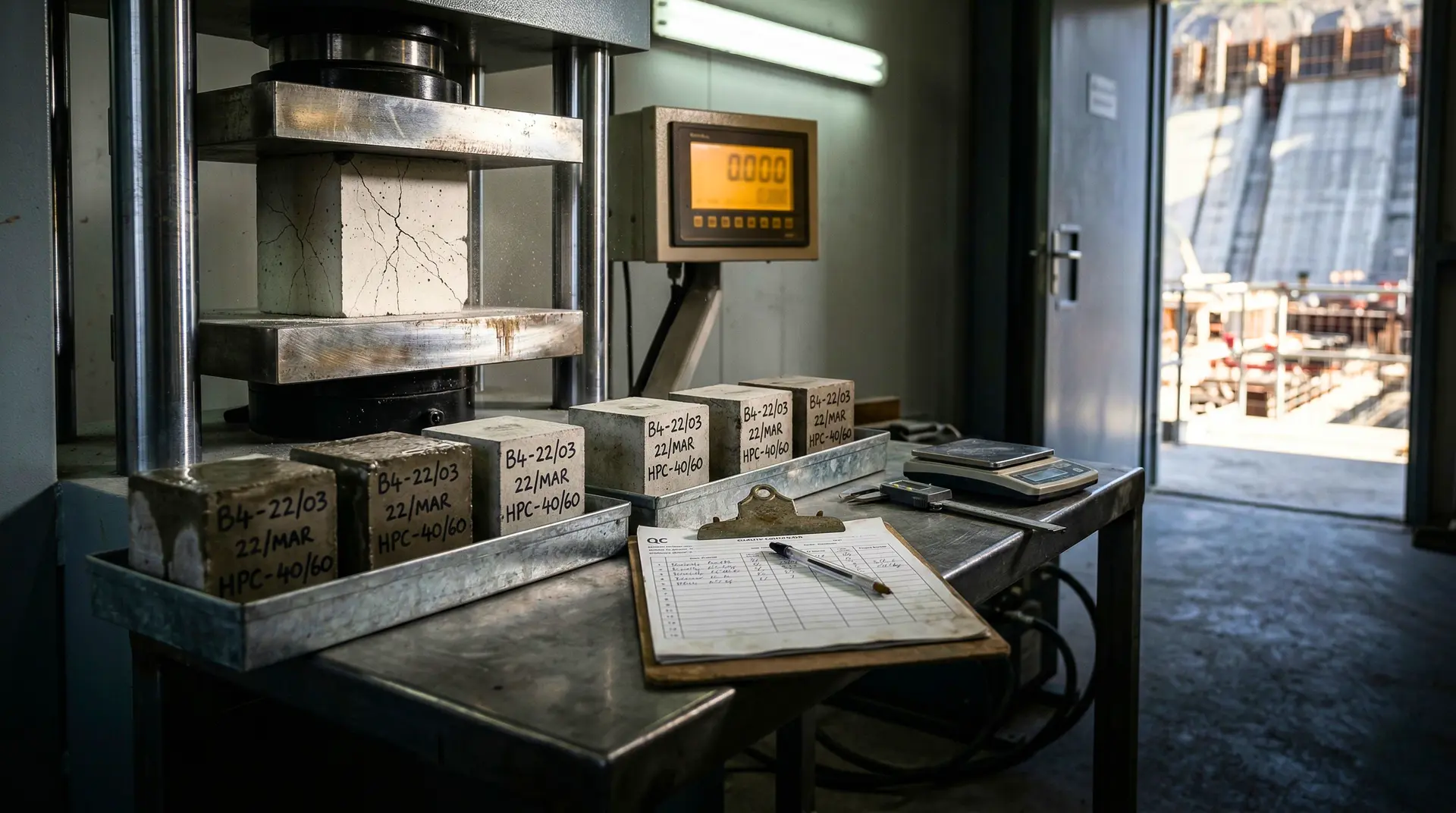
Laboratory setup
The site laboratory must be fully equipped, staffed, and calibrated before production begins. On a dam project placing 300 cubic metres per day, the lab generates 30 to 60 cube specimens daily. The laboratory is not a support function; it is the decision engine for every placement approval, every batch release, and every non-conformance disposition.
Batching plant QC: the first line of defence
Daily start-up checks
Every production day begins with the batching plant operator and QC technician running through a pre-production checklist:
- Weigh system calibration verification. Check all weigh hoppers (cement, SCMs, each aggregate size fraction, water, admixtures) against known test weights. Tolerance: within 1% for cement, SCMs, and water; within 2% for aggregates per IS 4925.
- Moisture content of aggregates. Measure the surface moisture of fine and coarse aggregates using speedy moisture tester or microwave oven method. The batching system must adjust water content and aggregate weight for each batch based on actual moisture. On Indian dam sites during monsoon, fine aggregate moisture can reach 8-12%, representing a significant volume of unaccounted water if not corrected.
- Aggregate stockpile inspection. Check for contamination between size fractions, segregation within stockpiles, and adequate separation between piles. Confirm that the correct aggregate is feeding the correct hopper.
- Cement and SCM silo levels and identity. Verify that the correct material is in each silo (mis-loading has caused entire pours to be rejected).
- Admixture dispensers. Verify correct admixture in each tank, check dispensing accuracy, confirm that dosage settings match the approved mix design for the day’s placement.
- Mixer condition. Inspect mixer blades for wear, check drum lining, verify mixing timer is functioning. Worn blades reduce mixing efficiency, producing non-uniform concrete.
- Pre-cooling system. If ice or chilled water is in use, verify ice-making plant output, chilled water temperature (target: 2-5 degrees C), and ice hopper functionality.
Batch-by-batch monitoring
For each batch of concrete produced:
- Batch ticket generation. The automated batching system prints a ticket showing the target and actual weight of every ingredient, the batch time, and the mix designation. The QC technician reviews the ticket for any deviation beyond tolerance. Any batch with a deviation exceeding 3% on cement or water must be flagged for disposition.
- Visual inspection. The experienced operator observes the concrete discharge for consistency, colour, and workability. Changes in colour (too grey, too brown) can indicate incorrect proportions. Dry or stiff patches indicate mixing problems.
- Temperature at discharge. Measure the concrete temperature as it leaves the mixer or agitator. If pre-cooling is in use, this reading confirms the system is achieving the target. The discharge temperature is not the placing temperature (the concrete will gain heat during transport), but it must be low enough to allow for transit heat gain.
Site reference: This guide is available as a printable PDF field reference, formatted for tablets and site offices. Download it from our Resources page.
Concrete transport: protecting the mix
The concrete must arrive at the placement face in the same condition it left the batching plant: at the specified workability, at the specified temperature, without segregation, and within the specified time.
Transport methods at dam sites
Transit mixers (agitating trucks): Standard on most dam projects. The drum rotates slowly during transit, preventing segregation and maintaining workability. Capacity: 6-9 cubic metres per trip. Suitable for transit distances up to 30-45 minutes.
Non-agitating dump trucks with concrete buckets: Used on some sites where the placement face is accessible by road. Higher risk of segregation and slump loss than agitating equipment.
Crane and bucket: The concrete is discharged from the transit mixer into a crane-handled bucket (1-4 cubic metre capacity) and lifted to the placement face. This is the most common final delivery method for conventional dam concrete, especially when the dam height exceeds the reach of concrete pumps.
Cableway (cable crane): On narrow valley sites, a cableway spans the gorge and transports concrete buckets from the batching plant on one bank to the placement face on the dam. The Tala Hydroelectric Project in Bhutan, where PCCI’s leadership provided concrete technology services, used cableway systems for the 1,020 MW installation.
Conveyors: Belt conveyors can transport concrete at high rates over long distances. Segregation at transfer points and discharge points must be controlled with baffles and drop chutes.
Time and temperature limits
Maximum transit time: The concrete must be placed within the initial setting time of the mix, with a generous safety margin. Typical specification limits:
- IS 4926: Maximum 2 hours from the addition of mixing water, or before 300 drum revolutions, whichever occurs first. Discharge on site must be completed within 30 minutes of arrival.
- ASTM C94: Historically 90 minutes from mixing to discharge (the 2021 revision removed the default limit, requiring the purchaser to specify)
- For dam construction, where the batching plant is at the site, practical transit times of 30-45 minutes from batching to placement are typical
- At ambient temperatures above 35 degrees C: reduce to 30-45 minutes unless retarder dosage is increased, per ACI 305 recommendations
Temperature gain during transit: Concrete gains approximately 0.5-1.5 degrees C during transit, depending on ambient temperature, transit time, and container type. This gain must be accounted for in the pre-cooling design. The placing temperature specification applies at the point of placement, not at the batching plant discharge.
Verification at delivery: At the placement face, the QC technician measures:
- Temperature (calibrated thermometer inserted into the fresh concrete). Must be at or below the specification limit (typically 15-25 degrees C).
- Slump (IS 1199 / ASTM C143). Must be within the mix design tolerance (typically specified value plus or minus 25 mm).
- Visual assessment for segregation, bleeding, or abnormal appearance.
Any batch failing any of these checks is rejected. The concrete is not placed in the dam. On a project placing 500-1,000 cubic metres per day, rejecting 2-3 batches per shift is not unusual and is a sign that the QC system is working, not that it is failing.
Placement operations: where quality is built
Lift geometry
Conventional mass concrete for gravity dams is placed in lifts (horizontal layers). The lift height is determined by the thermal analysis: taller lifts retain more heat and develop higher peak temperatures.
- Typical lift height: 1.5 metres for conventional mass concrete (per IS 457 guidance)
- Maximum lift height: 1.5-3.0 metres, depending on thermal analysis results, section thickness, and cooling system capacity
- RCC lift height: 300 mm (compacted thickness), a fundamentally different approach from conventional concrete
Each lift is placed in sub-lifts (horizontal layers within the lift) to ensure adequate vibration. The sub-lift thickness must not exceed the effective depth of the immersion vibrator:
- Sub-lift thickness: 300-500 mm for conventional mass concrete
- Each sub-lift must be vibrated before the next is placed
- The vibrator must penetrate 50-150 mm into the previous sub-lift to consolidate the interface
Pre-placement checks (hold points)
Before concrete delivery begins for any lift, the following hold points must be cleared:
- Surface preparation complete. The previous lift surface has been green-cut (or mechanically prepared for cold joints), cleaned of all debris and standing water, and conditioned to saturated surface-dry (SSD) condition.
- Bedding mortar applied (for planned construction joints). A 10-20 mm layer of cement-sand mortar spread immediately before the first sub-lift is placed.
- Formwork inspected. Alignment checked, form ties tightened, form oil applied (only water-based form release agents for dam concrete; petroleum-based oils contaminate the surface and weaken bond at the next lift joint).
- Cooling pipes installed and pressure-tested. Every circuit tested at 2-3 bar for 15-30 minutes with no leaks. A leaking pipe during concrete placement creates a void, and repairing it after the concrete sets is extremely difficult.
- Embedded items positioned. Waterstops at contraction joints, instrumentation conduits, drainage pipes, gallery linings, and any other embedded elements verified for location and secure fixing.
- Thermal monitoring instruments placed. Thermocouples or resistance temperature detectors at specified locations within the lift, connected and reading correctly.
- QC sign-off. The site QC engineer formally approves the placement by signing the pre-placement checklist. Without this sign-off, the batching plant does not begin production.
Placement sequence
Concrete is placed starting at the lowest point of the lift and progressing upward (on sloped surfaces) or from one end to the other (on level surfaces). The goal is continuous advancement of the concrete face without trapping air pockets or creating cold joints within the lift.
Drop height control: Concrete must not free-fall more than 1.5 metres to prevent segregation. When the bucket or discharge point is higher, the concrete is directed through drop chutes, tremie pipes, or elephant trunks that break the fall and deliver the concrete to the bottom of the form without segregation.
Horizontal flow: Concrete should not be pushed horizontally more than 1-2 metres. Excessive horizontal flow causes the mortar to travel ahead of the aggregate, creating segregated zones. Place the concrete close to its final position.
Placement rate: The rate must be fast enough to maintain a “live” front (preventing cold joints within the lift) but controlled enough for the vibration crew to keep pace. Typical rates for conventional dam concrete: 20-60 cubic metres per hour per placement block, depending on the block size, equipment, and crew.
Vibration: the most operator-dependent quality variable
Equipment selection
For mass concrete with 75-150 mm maximum aggregate size, large immersion vibrators are essential:
- Diameter: 50-75 mm head
- Frequency: 9,000-12,000 vibrations per minute (150-200 Hz)
- Amplitude: 1.0-2.0 mm (peak)
- Radius of action: 200-400 mm depending on vibrator diameter and concrete consistency
Per ACI 309R, larger vibrators are more effective in mass concrete. A 75 mm vibrator has approximately twice the radius of action of a 40 mm vibrator.
Vibration procedure
- Insert the vibrator vertically into the fresh concrete at a rate of approximately 75-100 mm per second. Do not force it; let the vibrator’s own weight and oscillation draw it down.
- Penetrate 50-150 mm into the previous sub-lift to consolidate the interface between layers. This is critical for preventing honeycombing at lift boundaries.
- Hold at each insertion point for 10-30 seconds, until air bubbles cease rising to the surface and the surface develops a thin sheen of mortar. This is the visual cue for adequate consolidation.
- Withdraw slowly at approximately 25-50 mm per second. Rapid withdrawal leaves a void that the concrete cannot fill.
- Move to the next insertion point at a spacing of 1.5 times the radius of action (typically 300-600 mm centre-to-centre). Overlapping coverage ensures no zone is missed.
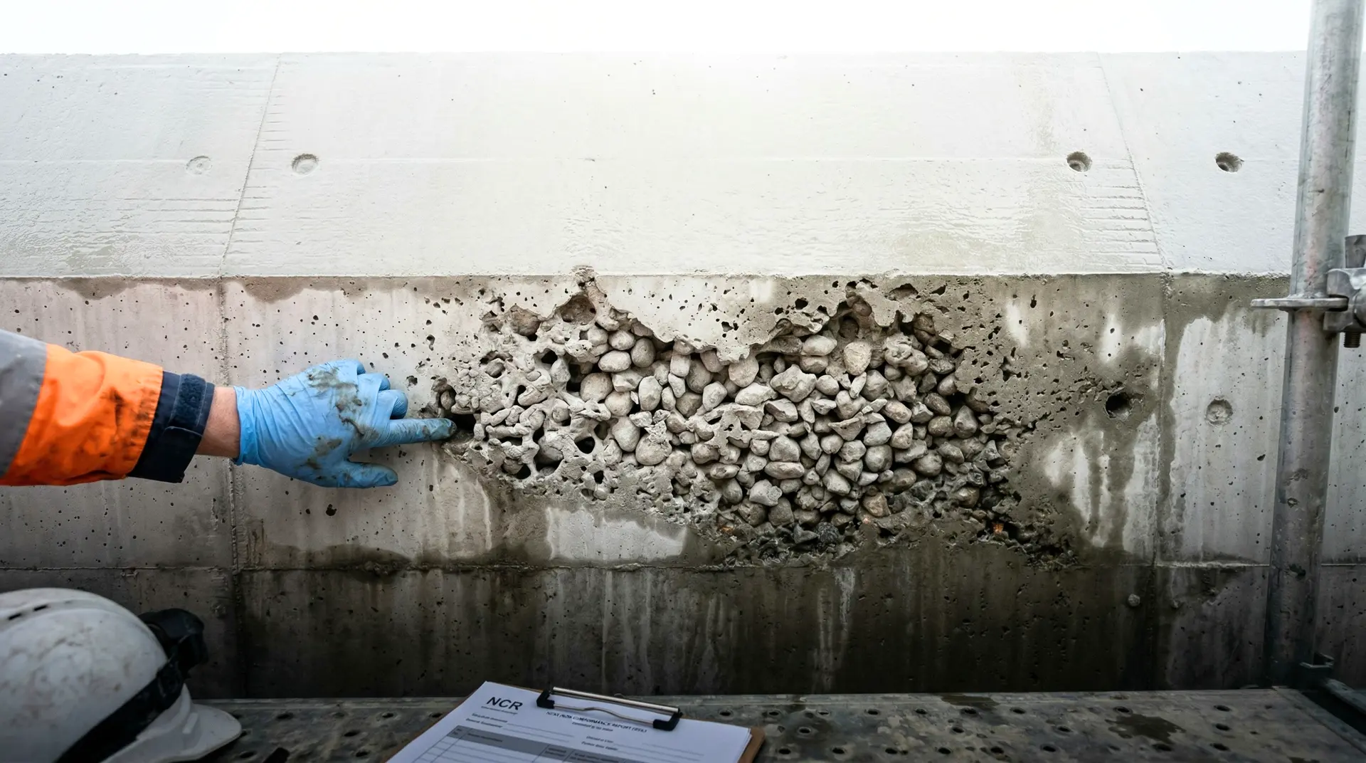
- Extra passes along formwork faces, around embedded items, and in corners. These areas are the most common locations for honeycombing and require additional attention.
Vibration near cooling pipes
Embedded cooling pipes are vulnerable to displacement and damage during vibration. The vibrator should not contact the pipe directly. Maintain a minimum clearance of 50-75 mm. Vibrate from both sides of the pipe to ensure concrete consolidates fully around it without moving it from its design position. After vibration, visually confirm the pipe has not shifted.
The over-vibration risk
Over-vibration is as damaging as under-vibration. When a vibrator is left in one location too long, or used on concrete that is already adequately consolidated, the heavy aggregate settles and the lighter paste rises. The result: aggregate-rich, paste-poor zones at the bottom of the sub-lift and excess laitance on top. This segregation by settlement creates the same honeycombing defect that under-vibration causes, but through the opposite mechanism.
The rule: Vibrate until the surface shows a thin mortar sheen and air bubbles stop. Then stop. Do not re-vibrate concrete that has already been consolidated unless it is still within its initial setting time and needs additional compaction for a specific reason.
Lift joint treatment: the most critical surface in the dam
Every horizontal construction joint is a potential plane of weakness. The bond between successive lifts determines the dam’s monolithic behaviour, its resistance to seepage, and its shear strength at the most heavily loaded planes.
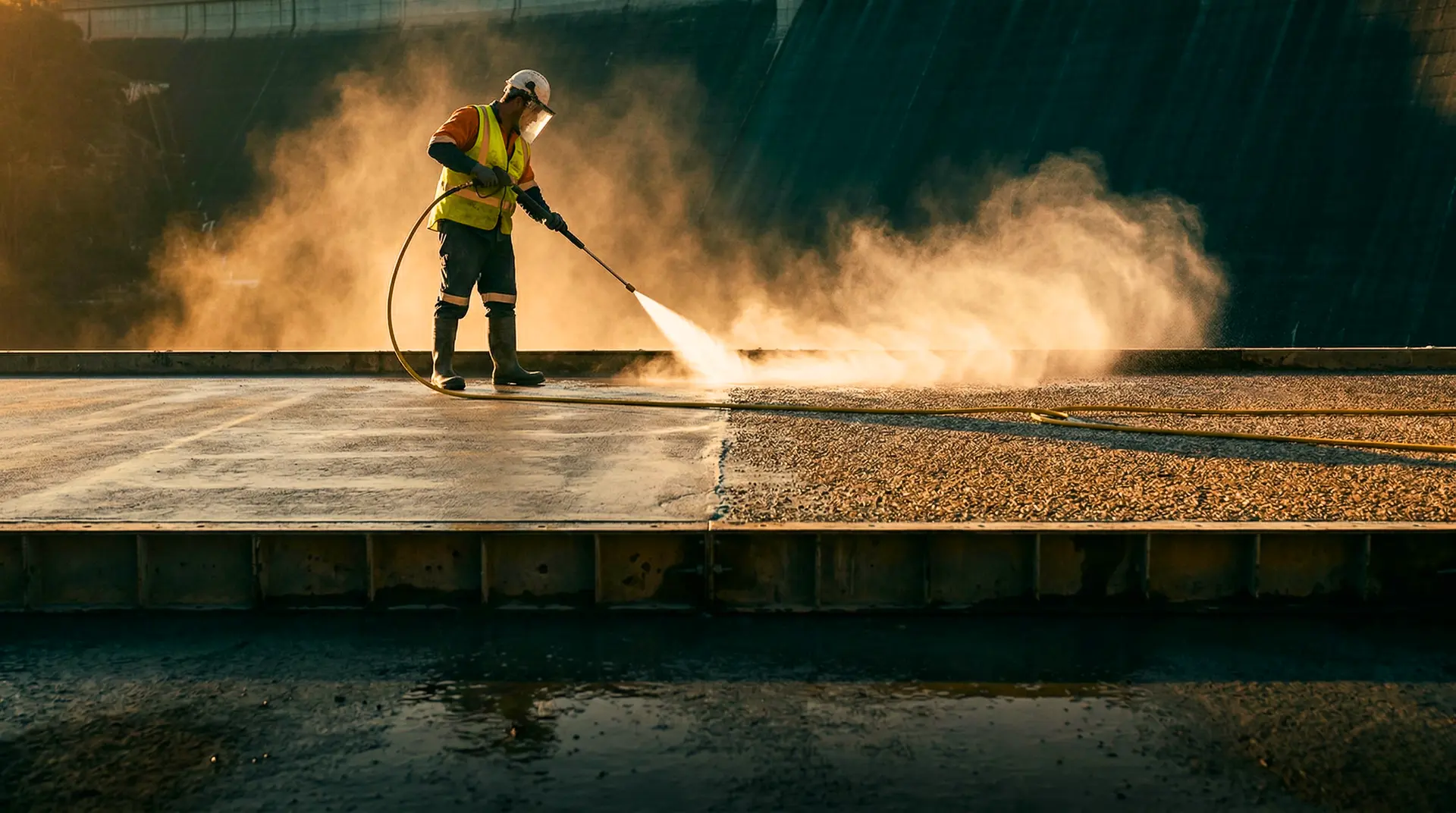
Green cutting
Green cutting is the preferred method for treating lift surfaces in conventional dam concrete. It is more efficient and produces a better bonding surface than mechanical preparation of hardened concrete.
What it is: Removing the laitance and weak mortar layer from the top of a placed lift using high-pressure water jets while the concrete is still semi-hardened (“green”).
Timing: 6-24 hours after placement, depending on ambient temperature and setting characteristics. The concrete should be firm enough to walk on without leaving footprints, but soft enough that water jets can remove the surface mortar without dislodging aggregate.
- At 30-40 degrees C ambient: green cutting window opens at 6-8 hours
- At 20-30 degrees C: 8-16 hours
- At 10-20 degrees C: 16-24 hours
- Below 10 degrees C: may extend to 24-36 hours
Test before starting: Press a piece of rebar into the surface. If it penetrates the mortar but not the aggregate, the concrete is ready for green cutting. If the rebar sinks through both mortar and aggregate, wait longer. If the rebar cannot penetrate the mortar, the green cutting window has passed and mechanical preparation is needed.
Water pressure: 20-50 MPa (200-500 bar) for conventional mass concrete green cutting. The exact pressure depends on the concrete’s age and strength at the time of cutting: lower pressures when cutting early in the window, higher pressures as the concrete gains strength. Pressures exceeding 70 MPa risk fracturing the substrate and should be avoided.
Target result: Coarse aggregate exposed to a depth of 3-6 mm across the entire surface. A uniform, rough texture with no smooth mortar patches remaining.
Coverage rate: With proper equipment and experienced operators, green cutting covers 5-10 times more area than mechanical chiselling, with less dust and less risk of substrate damage.
Surface cleaning and conditioning
After green cutting (or mechanical preparation for cold joints):
- Remove all loose material. Air-water jetting to clear debris, aggregate chips, and residual laitance.
- Inspection. The QC engineer walks the entire surface, checking for areas where the green cut was incomplete (smooth patches), areas where the surface was damaged (fractured aggregate), and any contamination (oil, dirt, construction debris).
- Moisture conditioning. The surface must be brought to saturated surface-dry (SSD) condition before the next lift is placed. This means the concrete is internally damp (no suction that would draw water from the fresh concrete) but the surface is free of standing water (which would dilute the paste at the interface and weaken the bond).
Achieving SSD: wet the surface thoroughly with clean water, then allow surface water to evaporate or remove it with compressed air, leaving a uniformly damp surface with no puddles. In hot weather, this may require repeated wetting because the surface dries rapidly. In humid conditions, ponded water may need to be blown off.
Bedding mortar
For planned construction joints (where the time between lifts exceeds the initial setting time of the underlying concrete), bedding mortar is applied to the prepared surface immediately before placing the fresh concrete.
- Mix: Cement-sand mortar at 1:1 to 1:2 ratio by weight, with SCM replacement matching the parent concrete mix
- Slump: 200-250 mm (flowable consistency)
- Thickness: 10-20 mm, spread uniformly across the prepared surface
- Timing: Must be placed immediately before concrete placement. Mortar that has begun to set before the fresh concrete arrives creates a double interface (mortar-to-old-concrete and mortar-to-fresh-concrete), which is weaker than a single properly bonded interface.
The bedding mortar fills surface irregularities and provides a paste-rich transition zone that compensates for the relatively paste-poor bottom of the fresh concrete lift.
Thermal management: the invisible quality parameter
Thermal cracking is the most consequential quality failure in dam concrete, and unlike honeycombing or surface defects, it develops invisibly inside the mass over days and weeks.
The thermal framework
Every degree matters. The peak temperature inside a mass concrete section equals approximately the placing temperature plus the adiabatic temperature rise from cement hydration. If the concrete is placed at 25 degrees C and the adiabatic rise is 30 degrees C, the peak reaches approximately 55 degrees C. If pre-cooling reduces the placing temperature to 15 degrees C, the peak drops to approximately 45 degrees C.
ACI 301 limits the temperature differential between the core and surface to 19-20 degrees C (35 degrees F). Beyond this threshold, tensile strain exceeds the capacity of young concrete, and cracks form.
Pre-cooling verification
At every point of placement, the QC technician measures the concrete temperature. The reading must be at or below the maximum placing temperature specified in the thermal control plan (typically 15-25 degrees C). This is a non-negotiable hold point.
If the concrete arrives above the specification limit by more than 1-2 degrees C:
- Reject the batch. Do not place it.
- Investigate the cause. Pre-cooling system underperforming? Transit time too long? Aggregate temperature higher than expected?
- Correct before resuming. Adjust ice quantity, chilled water temperature, or production rate.
Temperature monitoring during and after placement
Thermocouples or resistance temperature detectors (RTDs) embedded in each lift provide continuous temperature data:
- At the centre of the lift (maximum temperature location)
- At 300 mm from the surface (surface gradient monitoring)
- Adjacent to cooling pipes (cooling system effectiveness)
Monitoring frequency:
- First 72 hours: Every 4-6 hours (peak temperature typically occurs during this period)
- Days 3-21: Every 8-12 hours
- After 21 days: Daily readings until temperatures stabilize
Action triggers:
- Peak temperature exceeding the thermal model prediction by more than 3 degrees C: investigate and adjust cooling
- Core-to-surface differential approaching 19-20 degrees C: increase surface insulation, adjust cooling rate, or apply insulation blankets
- Cooling rate exceeding 0.5-1.0 degrees C per day (average mass temperature): slow down the cooling to prevent pipe cracks
Post-cooling operations
For conventional concrete dams with embedded cooling pipes:
Phase 1 (Initial cooling, days 1-21): Circulate chilled water at 5-10 degrees C, at 15-25 litres per minute per circuit. This extracts heat during the period of maximum heat generation (days 3-14). Monitor the differential between pipe location and mid-pipe location; it must not exceed 15-20 degrees C.
Phase 2 (Intermediate cooling, weeks 3 to months 3-12): Reduce flow rate to 10-15 litres per minute, increase water temperature to 10-15 degrees C. Maximum cooling rate: 0.5 degrees C per day average temperature decrease. This gradual cooling brings the concrete toward its long-term equilibrium temperature without creating damaging gradients.
Phase 3 (Final cooling, if required for arch dams): Cool to 5-10 degrees C below mean annual temperature to open contraction joints for grouting. Gravity dams do not require this phase.
Pipe grouting: After cooling operations are complete, each circuit is flushed and grouted with cement grout (w:c ratio 0.5-0.7) at 1-3 bar to fill the void and prevent the pipe from becoming a seepage path.
Site reference: Need this guide on site? Download the printable PDF version from our Resources page, formatted for field use on tablets and in site offices.
Curing: the patience that builds strength
Why dam concrete curing is different
Mass concrete in dams uses high SCM content (30-60% fly ash or GGBS replacement). Pozzolanic reactions are slower than Portland cement hydration and require sustained moisture and temperature for months, not days. A mass concrete mix designed for M20 at 365 days might test at only M12-M15 at 28 days. Cutting curing short sacrifices the long-term strength that the entire design depends on.
Curing methods for dam lifts
Ponding (horizontal surfaces): After the concrete has hardened sufficiently (typically 12-24 hours after placement), the lift surface is flooded with 25-50 mm of clean water retained by temporary earth or sand bunds. This is the most effective method for horizontal surfaces because it maintains 100% humidity and provides thermal buffering.
Wet hessian or burlap (formed surfaces): After formwork is stripped, wet hessian cloth is draped over the exposed surface and kept continuously moist. The hessian must not be allowed to dry out. On Indian dam sites in summer, with ambient temperatures exceeding 40 degrees C and relative humidity below 30%, the hessian can dry within 1-2 hours unless continuously sprayed.
Fog spraying: For surfaces where ponding and hessian are impractical (steep faces, complex geometry), fog nozzles create a continuous mist that maintains surface moisture. Less effective than ponding but suitable for vertical and inclined surfaces.
Curing compounds: Generally not recommended for lift surfaces in dam construction. Curing compounds form a membrane on the surface that prevents moisture loss, but this membrane can interfere with bond at the construction joint when the next lift is placed. Curing compounds may be used on surfaces that will not receive subsequent concrete (e.g., the downstream face of the dam, gallery walls).
Curing duration
- Minimum per IS 456: 7 days for OPC, 10 days for blended cements (PPC, PSC)
- Dam concrete specification (typical): 14 days minimum, extended to 21-28 days for mixes with SCM content above 35%
- High-altitude sites: 14-28 days, because cold temperatures slow hydration. Concrete cured at 5 degrees C develops strength at approximately half the rate of concrete cured at 20 degrees C.
Formwork stripping timing
Formwork must remain in place until the concrete has gained sufficient strength to support itself and resist thermal shock from exposure to ambient air. Typical requirements:
- Minimum concrete strength for stripping: 5-10 MPa (verified by maturity method, rebound hammer, or early-age cube tests)
- Minimum time: 24-72 hours for mass concrete, depending on ambient temperature and section thickness
- Thermal consideration: Stripping exposes the concrete surface to ambient air, creating an immediate temperature differential. If the core temperature is still elevated, premature stripping can trigger thermal cracking at the surface. In cold weather, stripping must be delayed or the surface must be insulated immediately after stripping.
Quality testing: measuring what matters
Testing schedule
Dam concrete testing extends far beyond the 28-day cube test used in building construction. The testing schedule spans the entire construction period and continues long after the last pour.
| Test Age | Purpose | Action if Fails |
|---|---|---|
| Fresh (every batch) | Temperature, slump, visual | Reject batch |
| 7 days | Interim strength check | Flag trend; investigate if below correlation |
| 28 days | Standard reference; interim acceptance | Investigate if below interim criterion; hold point for disposition |
| 90 days | Design age for some mixes | Formal acceptance/rejection decision |
| 180 days | Supplementary data | Refine correlations |
| 365 days | Design age for mass concrete | Final acceptance; structural reassessment if fails |
Sampling frequency
Per IS 456, the minimum sampling rate is one set per 50 cubic metres or per shift, whichever is more frequent. Each set typically includes:
- 3 cubes (150 mm) for the design-age test (90 or 365 days)
- 3 cubes for the 28-day interim test
- 2 cubes for the 7-day early indication test
- 1-2 cubes as reserve specimens
At 300 cubic metres per day, this means 6 sets = approximately 48-54 specimens per day, plus aggregate and fresh concrete tests.
In-situ testing
Laboratory specimens (cubes and cylinders) are cured under controlled conditions. The concrete in the dam is cured under field conditions: variable temperature, variable humidity, and the thermal effects of adjacent lifts. In-situ strength may differ from specimen strength by 10-20%.
Core extraction provides the definitive assessment of in-situ quality:
- When: After the concrete has reached the design age (90 or 365 days), or when specimen results indicate a potential deficiency
- Where: At locations representing different thermal histories (centre vs. edge of block, early vs. late placement), at construction joints, and at any location where surface inspection revealed defects
- How many: Per IS 456, a minimum of 3 cores from the suspected area. The average core strength must exceed 85% of the specified characteristic strength, and no individual core below 75%.
Non-destructive testing complements coring:
- Ultrasonic pulse velocity (UPV): IS 13311 Part 1. Maps concrete quality across large areas. Velocity above 4.5 km/s = excellent; 3.5-4.5 km/s = good; below 3.0 km/s = doubtful.
- Rebound hammer: IS 13311 Part 2. Quick surface hardness check, but influenced by surface condition and moisture. Use for relative comparison, not absolute strength determination.
- Impact echo: For detecting internal voids, delaminations, and the depth of defects.
Quality documentation: the permanent record
What gets documented
Every action in the concrete quality chain generates a record. On a dam with a 100-year design life, these records may be needed 50 years later when the structure is being assessed for continued service.
Batch tickets: Generated by the batching plant for every batch. Must record: mix designation, target and actual weights of all ingredients, batch time, mixer serial number, and any deviations.
Placement records (pour cards): One per placement (lift/block). Must record: block and lift number, date and time of start and finish, ambient temperature, concrete temperature at placement, concrete volume placed, number of batches, vibration crew details, any interruptions and their duration, weather conditions, and QC sign-offs at each hold point.
Temperature monitoring logs: Time-stamped temperature readings from every thermocouple in every lift, from placement through the end of the cooling period.
Test reports: Every fresh concrete test, every cube test, every aggregate test, every cement test, with specimen identification linked to the specific batch and placement.
Non-conformance reports (NCRs): For every deviation from the specification: concrete placed above the temperature limit, test results below the acceptance criterion, surface defects discovered during inspection, equipment failures during placement. Each NCR must document the deviation, the root cause analysis, the corrective action taken, and the disposition decision (accept, repair, or remove).
Hold points
Hold points are formal checkpoints where work must stop until the QC engineer provides written approval to proceed. On a dam concrete project, the standard hold points include:
- Before first production pour: All trial mixes approved, laboratory calibrated, mock-up completed
- Before each lift: Surface preparation verified, formwork inspected, cooling pipes tested, embedded items checked, pre-placement checklist signed
- During placement: Temperature check of each batch at the placement face
- After placement: Green cutting timing confirmed, curing initiated, thermal monitoring activated
- Before formwork stripping: Minimum strength or maturity verified
- At design-age test results: Formal acceptance or non-conformance decision
The non-conformance process
When concrete does not meet the specification, the non-conformance process must be methodical:
- Identify and document. What is the deviation? When and where was it discovered?
- Segregate. If the non-conforming concrete has not been placed, quarantine it. If it has been placed, mark the location on the dam layout drawings.
- Investigate. What caused the deviation? Was it a material problem, a batching error, a placement issue, or a testing error?
- Assess. Is the as-built concrete adequate for its structural purpose, even though it does not meet the specification? This assessment may require structural analysis by the design engineer.
- Decide. Three dispositions: accept as-is (with engineering justification), repair (grouting, honeycombing repair, surface treatment), or remove and replace (the most costly and disruptive option, reserved for serious deficiencies).
- Correct. Implement corrective actions to prevent recurrence.
- Record. Document the entire process in the NCR register.
Continuous improvement: learning from every pour
Pattern analysis
Over the course of a 3-5 year dam construction programme, thousands of test results, placement records, and NCRs accumulate. Analysing this data reveals patterns that individual results cannot:
- Strength trends over time. Are results drifting? Is the standard deviation increasing (indicating deteriorating production control)?
- Seasonal variations. Do placing temperature violations cluster in summer months? Do low-strength results correlate with monsoon-season aggregates?
- Crew performance. Does honeycombing occurrence vary by placement crew or shift?
- Equipment correlation. Is one transit mixer consistently delivering concrete at higher temperature or lower slump?
The feedback loop
The QC programme is not static. Every month, the concrete technology team reviews:
- Test result statistics (mean, standard deviation, coefficient of variation)
- NCR frequency and root causes
- Thermal monitoring data vs. model predictions
- Aggregate quality trends from the quarry
- Placement rate vs. cold joint risk
Adjustments are made: admixture dosages recalibrated for the current season, vibration crew retrained on areas showing recurring defects, aggregate processing modified to address grading changes as the quarry face advances, pre-cooling capacity increased for the approaching summer.
The QC engineer’s daily rhythm
A typical day on a dam project, from the QC engineer’s perspective:
05:30. Arrive at the batching plant. Check moisture content of aggregates. Verify pre-cooling system operation. Review the day’s placement plan.
06:00. Pre-placement inspection of the active block. Walk the lift surface: green cutting complete? Surface clean? SSD condition? Cooling pipes tested? Formwork aligned? Sign the pre-placement checklist.
06:30. First batch. Measure slump and temperature at the placement face. Release the batch for placement.
07:00-17:00. Continuous monitoring. Temperature and slump tests on every batch (or at the specified frequency). Watch the vibration crew. Sample cubes at the required frequency. Record everything on the placement card.
12:00. Midday temperature check. If ambient temperature is climbing, verify that placing temperature is still within limits. Coordinate with the pre-cooling plant operator if needed.
17:00. Placement complete for the day. Initiate curing. Confirm thermal monitoring system is recording. Calculate the green cutting window for this lift.
02:00 (next day). Green cutting crew arrives. QC technician on night shift supervises the green cutting operation, verifying timing and surface quality.
Repeat. For 3-5 years. For every lift, in every block, on every monolith.
The long view
The concrete placed today will be tested at 28 days, at 90 days, at 365 days. The core taken from this lift at year five will be compared to the cube cast this morning. The seepage reading taken at year fifty will reflect the bond achieved at this lift joint.
Quality control in dam construction is not a phase of the project. It is the project. Every batch ticket, every temperature reading, every vibrator insertion, every green cut, every cube specimen is a data point in a decades-long record of structural integrity.
The dam does not care about the production schedule. It does not care about the contract milestones. It cares only about the quality of the concrete that forms its body and the joints that hold it together. The QC programme exists to ensure that when the reservoir fills and the water pushes against the dam for the first time, the concrete pushes back.
Download: This entire guide is available as a printable PDF field reference, formatted for dam site use. Keep it on your tablet, print it for your site office, or share it with your QC team.
PCCI’s QA/QC Systems and Laboratory Programs service brings leadership with 40+ years of expertise to this daily discipline. From laboratory setup to thermal monitoring, from mix design optimization to construction troubleshooting, PCCI provides the hands-on quality engineering that transforms specifications into structures.