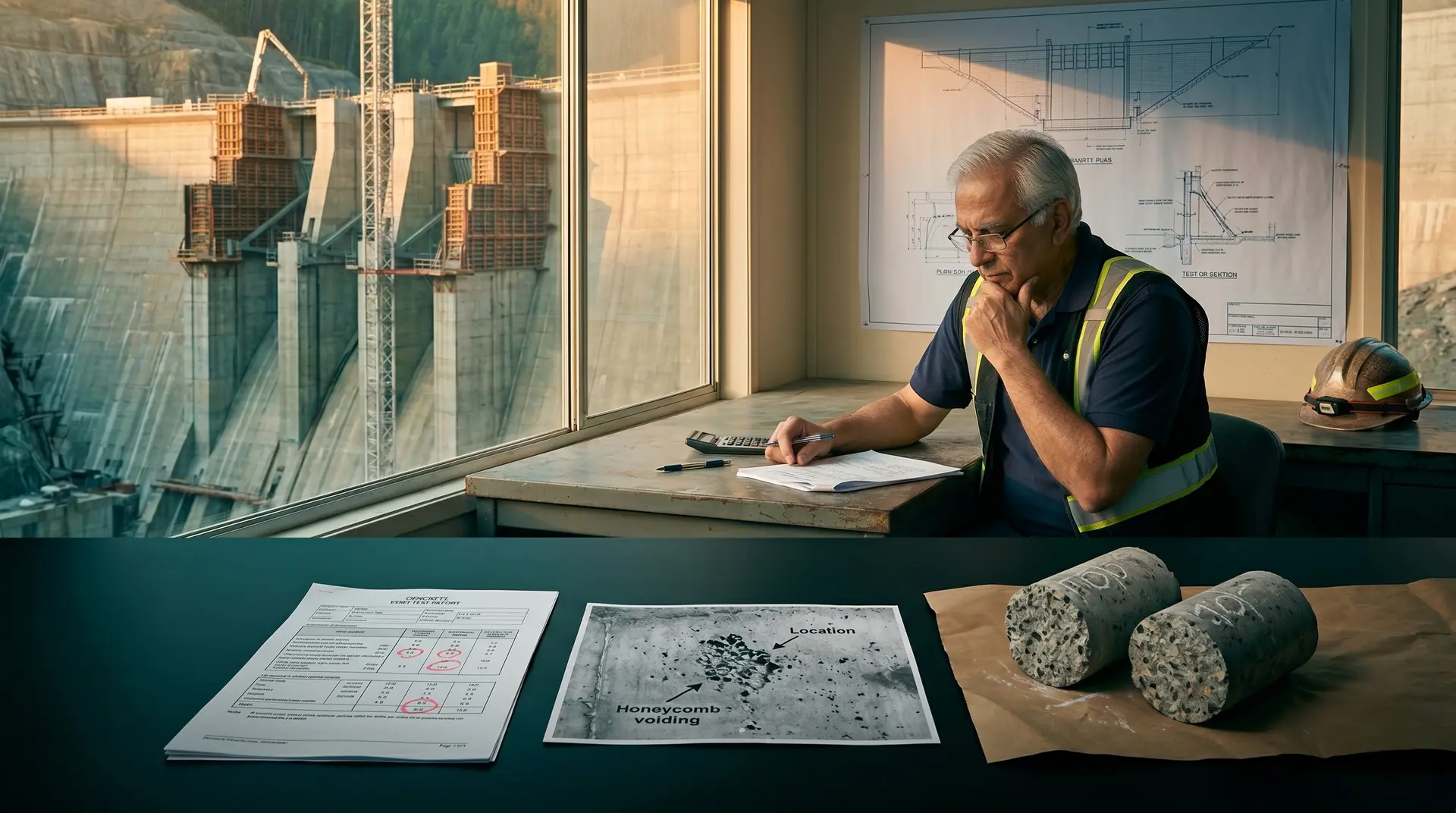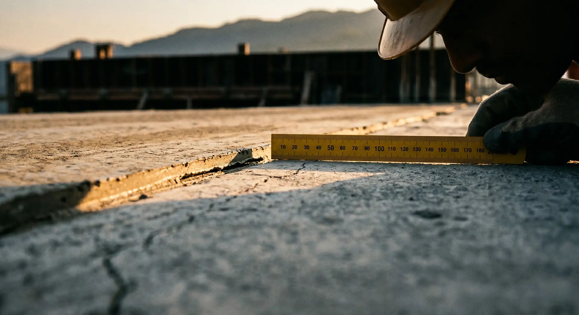
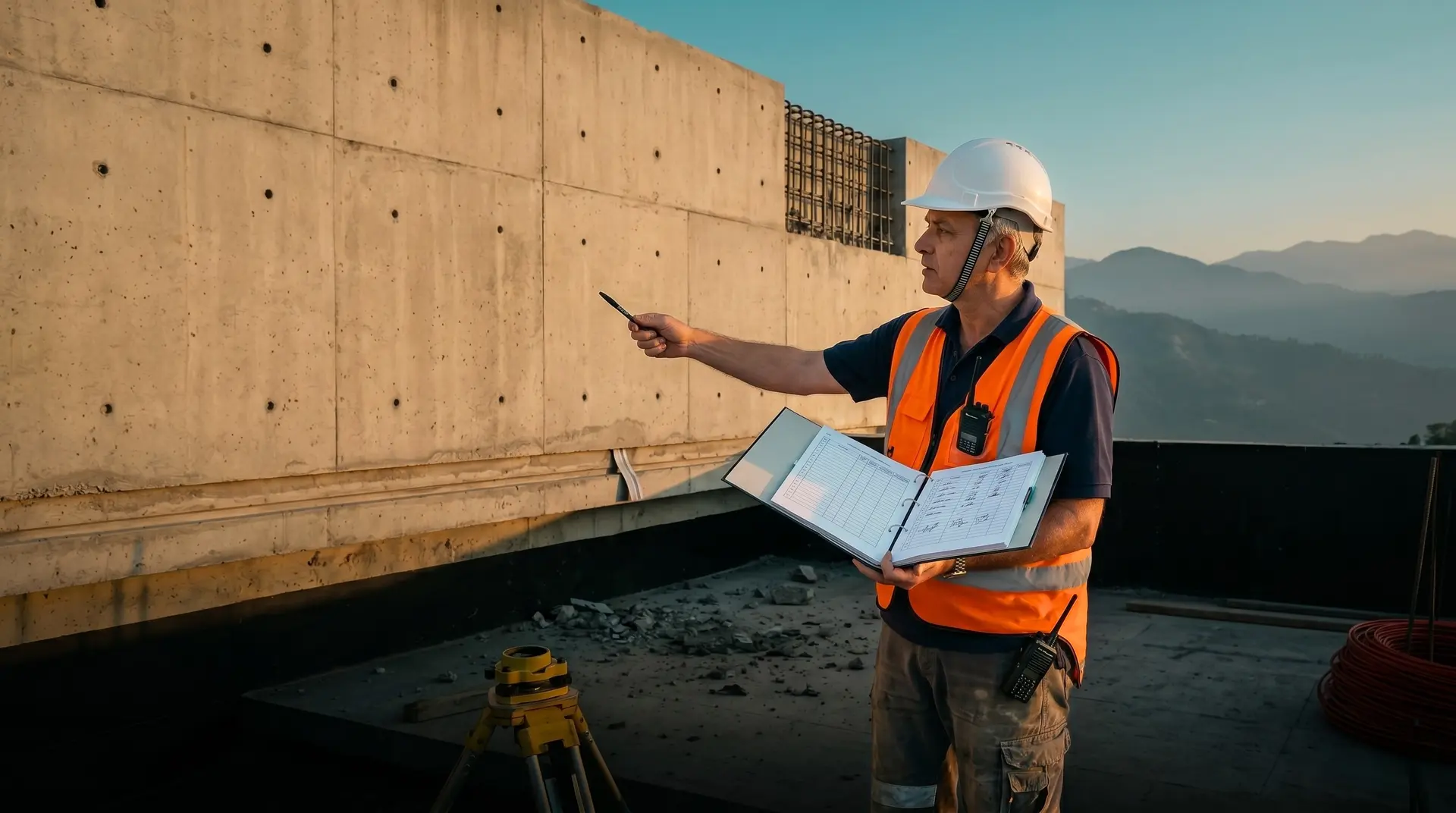
Hold and Witness Points are the enforceable inspection gates in a dam concrete project’s Inspection and Test Plan: 18 gates cover every realistic pour-cycle checkpoint from aggregate source acceptance through post-pour disposition. A Hold Point requires written release by the Engineer before work proceeds; a Witness Point requires advance notification but lets work proceed if the Engineer does not attend within the grace window. The 18-point register sits inside four frameworks: FIDIC contract, ISO 9001:2015, ACI 311.4R, and India-specific BIS provisions.
The QA/QC plan a Contractor submits at the start of a hydropower dam project is paper. The Hold and Witness register is what converts that paper into enforceable construction-phase control. Each H&W point is a moment where the Engineer can legitimately stop work, demand evidence, and refuse to release until the Contractor produces it. Each missing point is a gap the project will discover later as a cold joint, a misaligned waterstop, a cracked lift, or a strength failure.
Eighteen points cover every realistic gate a dam-concrete pour cycle needs. Fewer leaves enforcement gaps; more produces friction without additional protection. The register sits inside four regulatory layers: the FIDIC Red Book 2017 (Conditions of Contract for Construction) contract, ISO 9001:2015 (Quality management systems: Requirements) quality management, ACI PRC-311.4-05 (Guide for Concrete Inspection) concrete inspection guide, and India-specific BIS provisions including IS 456:2000 and the Central Water Commission’s DRIP Phase II programme guidance. This brief walks each of the 18 points in order, with the classification, the verification basis, the evidence required, the common Contractor failure mode, and the PCCI-recommended practice.
How is the H&W register classified?
Before the 18 points themselves, the classification grammar.
| Symbol | Name | Behaviour |
|---|---|---|
| H | Hold Point | Mandatory verification gate. Work shall not proceed until released by the Engineer in writing. |
| W | Witness Point | Notification gate. Contractor notifies Engineer 24-72 hours in advance. If Engineer does not attend within the grace window, work may proceed and Engineer reviews records afterwards. |
| R | Review | Document or submission review without site attendance required. |
| S | Surveillance | Routine spot check, ad-hoc, no advance notification required. |
The 18-point register below uses H and W exclusively because these are the contractually-binding gates. R and S points exist in a complete ITP but do not affect the schedule the same way.
Notification window discipline
Every H and W line item in the ITP must have an explicit notification window (24, 48, or 72 hours). Missing windows is the most common reason H&W register disputes escalate to the dispute board. PCCI's standard practice is to publish the notification matrix at the start of the project so neither party can later claim ambiguity.
Stage A: Pre-pour materials and design gates (5 points)
These five gates are project-level. They are cleared once at pre-construction or when a material source changes. They are not pour-specific.
Point 1: Aggregate source acceptance and qualification (H)
Verification basis: Petrographic examination, alkali-aggregate reactivity testing (AAR) per ASTM C1260 (Accelerated Mortar-Bar Test) and ASTM C1293, deleterious materials testing, grading analysis per IS 383, and water absorption.
Evidence required: Lab test reports from accredited laboratory; petrographic report identifying mineralogy; AAR classification (innocuous, potentially reactive, or reactive); grading curves for fine and coarse aggregate per applicable zone or MSA.
Common failure mode: Submitting test reports from quarry samples that do not represent the actual production stockpile. Sampling protocol must be documented and Engineer-witnessed.
PCCI practice: Insist on Engineer-witnessed sampling at the production stockpile. Maintain a quarterly re-qualification cycle for the project duration.
Point 2: Cementitious material qualification (H)
Verification basis: Cement, fly ash, slag, and silica fume each qualified independently against ASTM and IS specifications. Cement per ASTM C150 or IS 269 / IS 12269; fly ash per ASTM C618 Class F or IS 3812 Part 1 Grade I; slag per ASTM C989 or IS 16714:2018 (Ground Granulated Blast Furnace Slag for use in cement, mortar and concrete); silica fume per ASTM C1240 or IS 15388.
Evidence required: Manufacturer test certificates for each lot; independent third-party verification testing for the project’s first lot of each material; storage protocol approval.
Common failure mode: Accepting manufacturer certificates without independent verification on first lot. Fly ash chemistry and fineness variability is the single biggest source of trial-mix surprises later.
PCCI practice: Test the first lot of each cementitious material against both ASTM and IS specifications so the Lender’s Technical Advisor can invoke either at acceptance. Cross-references PCCI’s mix design and performance concrete service.
Point 3: Trial mix approval and design mix submission (H)
Verification basis: Trial mix programme covering ordinary, mass, and high-strength concrete grades as required; 28-day cube and cylinder strength results; durability test results (water permeability, chloride permeability if applicable); thermal property qualification for mass concrete.
Evidence required: Trial mix register with each iteration documented; all strength and durability test data; mix design submission document (typically 30 to 80 pages depending on project complexity); Engineer approval signature.
Common failure mode: Submitting trial mix results without the iteration history. The Engineer cannot verify the proportioning logic if only the final mix is presented.
PCCI practice: Maintain a single trial-mix register that cross-tabulates cube and cylinder strength results against the same mix IDs, supporting dual-code acceptance under both ACI 211 and IS 10262 mix proportioning frameworks.
Point 4: Batching plant calibration certificate (H)
Verification basis: Calibration of all weigh hoppers (cement, fly ash, water, aggregate); admixture dispensers; mixer efficiency test; moisture probes on aggregate bins.
Evidence required: Calibration certificates from accredited agency; tolerance compliance documented (per ACI 304R: ±1% on cementitious, ±2% on aggregate, ±1% on water, ±3% on admixture); plant log-book.
Common failure mode: Initial calibration cleared but no recalibration schedule established. Plant drift over six months is a frequent root cause of strength variability discovered too late.
PCCI practice: Mandate quarterly recalibration with the Engineer witnessing at least one calibration cycle per quarter.
Point 5: Site laboratory setup and equipment calibration (H)
Verification basis: Lab layout per project specification; equipment inventory (compression testing machine, slump cone, air entrainment meter, thermometer, oven, sieve set); calibration certificates for all equipment.
Evidence required: Lab commissioning report; equipment calibration register; lab personnel qualification records; cube and cylinder mould inspection record.
Common failure mode: Compression testing machine not recalibrated against an externally certified reference; loading rate drift produces apparently acceptable but actually-failing strength results.
PCCI practice: Independent third-party calibration of the compression testing machine before the first acceptance test, and at six-month intervals throughout construction.
Stage B: Pre-pour pour-specific gates (5 points)
These five gates are cleared per pour. They produce a Pour Card or Concrete Placement Permit that is the operational artefact for that placement.
Point 6: Pour card / Method Statement approval (H)
Verification basis: Pour-specific method statement covering pour volume, lift thickness, placement sequence, equipment, contingency plan, weather forecast, and crew assignment.
Evidence required: Approved pour card with Engineer signature; weather forecast attached (especially relevant for hot weather concreting per IS 7861 Part 1 above 40°C ambient or cold weather per Part 2 below 5-10°C).
Common failure mode: Pour card submitted same-day as the planned pour, denying the Engineer adequate review time.
PCCI practice: Pour card submission at least 48 hours before scheduled placement, with 24-hour confirmation when the weather forecast is finalised.
Point 7: Formwork inspection (H)
Verification basis: Alignment within tolerance (typically ±5 mm per IS 14687 guidelines for falsework); plumb and level; rigidity and bracing adequacy; release agent applied evenly without contamination of reinforcement; joints sealed against grout loss; access for vibration; safe scaffold access for inspectors.
Evidence required: Signed formwork inspection sheet; alignment survey if dam face geometry; photographs.
Common failure mode: Joint gaps unfilled producing honeycomb at the formed face; release agent contaminating rebar reducing bond.
PCCI practice: Engineer walks every linear metre of formwork edge before release; close-up photographs filed against the pour card. Cross-references PCCI’s 12 concrete defects an Owner’s Engineer catches.
Point 8: Reinforcement inspection (H)
Verification basis: Bar size, grade, and spacing against approved drawings; lap lengths meeting code (IS 456 or ACI 318 as applicable); cover blocks installed at specified spacing; surface free of loose rust, oil, mill scale, mud, or release agent contamination.
Evidence required: Signed reinforcement inspection sheet; bar bending schedule cross-checked; cover block specification compliance; photographs.
Common failure mode: Cover blocks dislodged or too widely spaced producing sagging cages and locally inadequate cover; tying not tight enough to maintain position during vibration.
PCCI practice: Walk-through inspection with the rebar foreman, not just the QC supervisor; spot-check tie tightness physically.
Point 9: Embedded items inspection (H)
Verification basis: Waterstop alignment and continuous embedment (centre axis coincident with joint opening); splices visually inspected for bubbles, cracks, voids, and burns; dowels, anchors, and instrumentation embedments positioned per drawings and stabilised against displacement during placement.
Evidence required: Signed embedded items inspection sheet; waterstop splice register; instrumentation activation pre-pour confirmation; photographs of every waterstop splice.
Common failure mode: Waterstop displacement during concrete placement is among the most frequently-occurring quality failures on dam projects. The Association of State Dam Safety Officials notes that poor waterstop installation frequently occurs across dam construction.
PCCI practice: Physical anchoring of waterstops every 300 to 500 mm; pre-pour walk-through with the embedment installer; Engineer witnesses any new splice on the pour day.
Point 10: Lift surface preparation (H)
Verification basis: Laitance and weak surface mortar fully removed by high-pressure water washing (per USACE ETL 1110-2-343 as equivalent to wet sandblasting); coarse aggregate exposed but not undermined; surface kept saturated-surface-dry (SSD) at moment of next placement; bedding mortar placed where specified (mandatory on upstream RCC faces).
Evidence required: Surface preparation inspection sheet; photographs before and after cleaning; bedding mortar mix design and placement record; lift exposure time logged.
Common failure mode: Inadequate cleaning leaves laitance bond breaker; delayed cleaning lets laitance harden; surface dries between cleaning and placement; bedding mortar layer skipped or applied too thinly. USACE ETL 1110-2-343 treats lift surface preparation as a primary risk for cold-joint failure.
PCCI practice: Photographs of the cleaned surface filed against the pour card; bedding mortar witnessed during placement; lift exposure time stamped in the construction log.
Stage C: During-pour gates (4 points)
These four gates are real-time during the pour. Each requires the Engineer or designate present at the activity.
Point 11: Pre-pour concrete acceptance (W)
Verification basis: Slump within specification (typically 25-75 mm for mass concrete interior, 50-100 mm for cover); air content within specification (where air entrainment is required); concrete temperature at delivery (target 10-32°C per ACI 301); sampling for compressive strength and other tests.
Evidence required: Concrete delivery ticket; fresh test results (slump per ASTM C143 or IS 1199, air per ASTM C231, temperature); sampling record.
Common failure mode: Slump out of range corrected on-site by adding water (prohibited by every code); rejected loads rebatched and re-tested without honest documentation.
PCCI practice: Mandatory rejection of any load failing fresh tests; no on-site water addition under any circumstance.
Point 12: Placement supervision (W)
Verification basis: Lift thickness within specification (typically 300-500 mm for mass concrete); placement sequence respects pre-pour planning; vibration adequate (typical 50-150 mm penetration into previous layer); no segregation; no exceeded freefall distance.
Evidence required: Placement supervision record; vibrator log; lift thickness measurements.
Common failure mode: Lift thickness exceeded when the Contractor falls behind schedule, producing inadequate consolidation; freefall from height producing segregation.
PCCI practice: Continuous Engineer presence for the full duration of mass concrete placements; intermittent walk-through for smaller pours.
Point 13: Pour temperature monitoring (W)
Verification basis: Concrete-as-placed temperature; ambient temperature at intervals during placement; thermocouples or temperature loggers active at depth and surface of the lift; subsequent monitoring through peak temperature (typically 24-72 hours post-placement) and ramp-down.
Evidence required: Temperature log (continuous, hourly recording); ambient log; thermocouple installation record; transmission to thermal control engineer per the thermal control plan.
Common failure mode: Thermocouples installed but not activated; temperature data not reviewed in real-time so the differential limit (typically 19.4°C / 35°F core-to-surface per ACI 207 practice) is exceeded without intervention.
PCCI practice: Real-time temperature dashboard with alarm thresholds; thermal control engineer notified within 30 minutes if any alarm trips.
Point 14: Embedment activation and instrumentation (W)
Verification basis: All embedded instrumentation (thermocouples, strain gauges, piezometers, pore pressure cells) confirmed active and recording before concrete reaches the embedment location.
Evidence required: Pre-pour activation record; reading captured at the moment concrete reaches the embedment; baseline reading filed.
Common failure mode: Instrumentation present but not activated, leaving the dam with sensors but no baseline. Rectification post-pour is not possible.
PCCI practice: Activation witnessed by the instrumentation specialist immediately before placement at that lift location; signed against the pour card.
Stage D: Post-pour gates (4 points)
These four gates run from immediately after placement through final acceptance. They close the pour card.
Point 15: Curing initiation and protection (W)
Verification basis: Curing initiated within the time specified (typically immediately on finishing, no later than initial set); curing method per specification (water curing, curing compound, or impermeable cover); duration per specification (typically 7 days minimum for OPC mixes, 14 to 28 days for high-SCM mass concrete); freeze protection in cold weather, moisture protection in hot weather.
Evidence required: Curing initiation time stamped; curing method documented; protection in place verified; daily curing log.
Common failure mode: Curing delayed past initial set producing plastic shrinkage cracking; curing terminated too early because the schedule pressures the Contractor to strip forms.
PCCI practice: Curing log maintained daily; spot-check moisture status throughout the required period.
Point 16: Strength testing acceptance (H)
Verification basis: Compressive strength test results at scheduled ages: 7-day, 28-day, 56-day for mass concrete, 90-day where the specification calls for late-age verification of mass concrete. Tests per IS 516 Part 1/Sec 1:2021 (Compressive and Flexural Strength of Concrete) (cubes) or ASTM C39 (cylinders). Acceptance criteria per IS 456 Clause 16 or ACI 301 / 318 as applicable.
Evidence required: Test certificates from the project lab; cube or cylinder casting record; curing record of the specimens; acceptance computation showing characteristic strength satisfied.
Common failure mode: Specimens cured outside the controlled lab tank, producing apparently failing results that are actually specimen-handling failures; non-conformance review delayed until the next pour is already in progress.
PCCI practice: Daily review of strength results; immediate escalation if any test trails the target by more than 10%. Cross-references PCCI’s concrete acceptance criteria for dam QA/QC.
Point 17: Surface finish inspection (W)
Verification basis: Formed face inspection for honeycombing, blowholes, alignment defects, and cover issues (see 12 concrete defects an Owner’s Engineer catches); unformed surface inspection for finish class compliance, plastic shrinkage cracks, and trowel marks.
Evidence required: Surface defect register; photographs; repair proposals where applicable.
Common failure mode: Defects identified but not catalogued; repair proposals proceeding without Engineer approval; cosmetic repair masking structural defects.
PCCI practice: Defect register filed against the pour card; no repair proceeds without Engineer-approved repair method statement.
Point 18: Non-conformance review and accept/repair/reject disposition (H)
Verification basis: Any deviation from specification documented in a Non-Conformance Report (NCR); root cause analysis; disposition decision (accept-as-is, accept-with-condition, repair to specified method, or reject).
Evidence required: NCR with Engineer disposition signature; repair method statement if applicable; verification testing if repair is invoked.
Common failure mode: NCRs informally resolved on-site without documentation; disposition decided by Contractor QC rather than Engineer; repair method not pre-qualified.
PCCI practice: Every NCR formally raised, tracked, and dispositioned per the accept/repair/reject decision framework with Engineer signature before the pour card is closed.
How is the H&W register used in practice on a dam project?
The 18-point register operates as a per-pour artefact through the Pour Card. For each scheduled placement, the Contractor opens a pour card listing every applicable H&W point for that specific pour. Stage A points are project-level and pre-cleared. Stage B points are cleared the day of the pour. Stage C points are signed in real-time during the pour. Stage D points are signed in the days following the pour, with strength acceptance (Point 16) usually the last to clear at 28 days or 56 days.
The pour card is closed only when all Stage D items clear. The closed card, with all H/W signatures, supporting evidence (test reports, photographs, temperature logs), and any NCR dispositions, becomes the artefact the Lender’s Technical Advisor reviews at acceptance. It is also the source document if a non-conformance review escalates to the dispute board under the FIDIC Particular Conditions.
PCCI’s working practice on Bhutan and India projects is to publish a single project-wide signature authority matrix at mobilisation, listing exactly which named individuals (Engineer, Owner’s Engineer, Contractor’s QC, TPI) can release which Hold Points, with delegation rules for absences. This pre-empts the most common procedural dispute on dam projects: ambiguity about who can sign the release form on the day.
For the broader QA/QC plan structure that the H&W register sits inside, and the larger context of QA/QC discipline on hydropower dam projects, see PCCI’s adjacent technical briefs.
Closing: the artefact that wins disputes
The 18-point H&W register is the difference between a dam concrete project that runs cleanly and one that does not. Disputes that escalate to the dispute board almost always involve a missed or ambiguous H&W gate. Projects that close their pour cards diligently, with every H and W signed and every NCR dispositioned, produce a record that the LTA cannot challenge at acceptance.
PCCI’s leadership authored the Concrete Quality Control Manual for Punatsangchhu-1 HEP (1,200 MW) in Bhutan during the project’s construction phase; the manual operationalised the H&W register approach at the dam-concrete pour level. The same leadership led the QC programme on Mangdechhu HEP (720 MW) from inception to commissioning, where the same H&W discipline applied across the dam, intake, and powerhouse mass-concrete placements.
For project advisory on H&W register design or independent review of an in-flight QA/QC programme, the Owner’s Engineer / Independent Review service provides the senior practitioner second opinion that catches enforcement gaps before they become construction-phase failures. For the QA/QC system itself, see QA/QC systems and lab programs. For construction-phase troubleshooting on disputes already in progress, see construction troubleshooting and RCA.
Eighteen gates. One register. Every pour traceable from aggregate source to acceptance. That is what enforceable dam concrete quality looks like.