Concrete for dam intake structures and gate slots is governed by precision rather than strength: gate grooves and seal seats require tolerances of plus or minus 2 mm or tighter, delivered through first-stage and second-stage placement, non-shrink encasement of embedded metalwork, and abrasion-resistant hydraulic surfaces, with every dimension verified before the reservoir fills.
Every cubic metre of water that enters a hydroelectric dam passes through an intake structure. Every flood that threatens the dam is controlled by gates seated in precision-formed concrete slots. These components do not receive the attention that the dam body or spillway commands, but their failure is equally consequential.
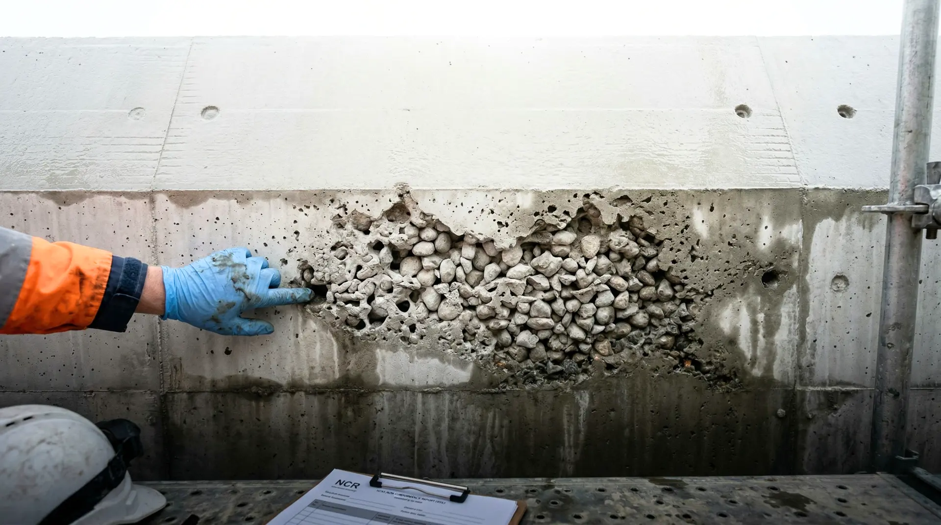
A gate that cannot close because the slot is misaligned leaves a dam without flood control. An intake surface that erodes creates turbulence that reduces turbine efficiency and accelerates wear on downstream components. Concrete honeycombing around embedded metalwork provides a pathway for seepage that corrodes the embedded steel from the inside.
Intake structures and gate slots represent a category of dam concrete work where the tolerance requirements of precision engineering meet the material realities of concrete construction. The challenge is not strength: most intake concrete specifications call for 30 to 50 MPa, which is achievable with standard materials. The challenge is precision, surface quality, and the coordination between concrete and embedded metalwork that must function together for the life of the dam.
Anatomy of a Dam Intake Structure
A dam intake structure typically comprises several concrete elements, each with different requirements.
Intake Tower or Bell Mouth
The intake tower collects water from the reservoir and directs it toward the penstock or tunnel. The concrete forming the bell mouth (the flared entrance) must be hydrodynamically smooth to minimise head losses and prevent cavitation. Flow velocities at the bell mouth typically range from 1 to 5 m/s, lower than spillway velocities but sufficient to cause erosion of poor-quality concrete over decades.
Trashrack Structure
The trashrack prevents debris from entering the waterway. The concrete structure supporting the trashrack screens must accommodate the trashrack guides (typically stainless steel angles or channels), provide adequate bearing area for the screen weight plus hydrodynamic loads, and allow for removal and replacement of individual trashrack panels.
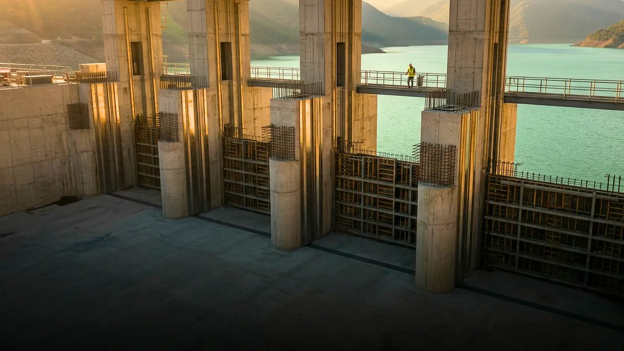
Gate Slots
Gate slots house the slide gates, radial gates, or stop-log gates that control water flow. They are the most dimensionally critical concrete elements in the entire dam. The gate slot concrete must provide:
- A smooth, precisely dimensioned groove for the gate to travel in
- A flat, smooth seal seat where the gate rubber or metallic seal contacts the concrete
- Structural capacity to resist the full hydrostatic load transferred from the gate
- Durability against abrasion from gate operation and sediment-laden flow
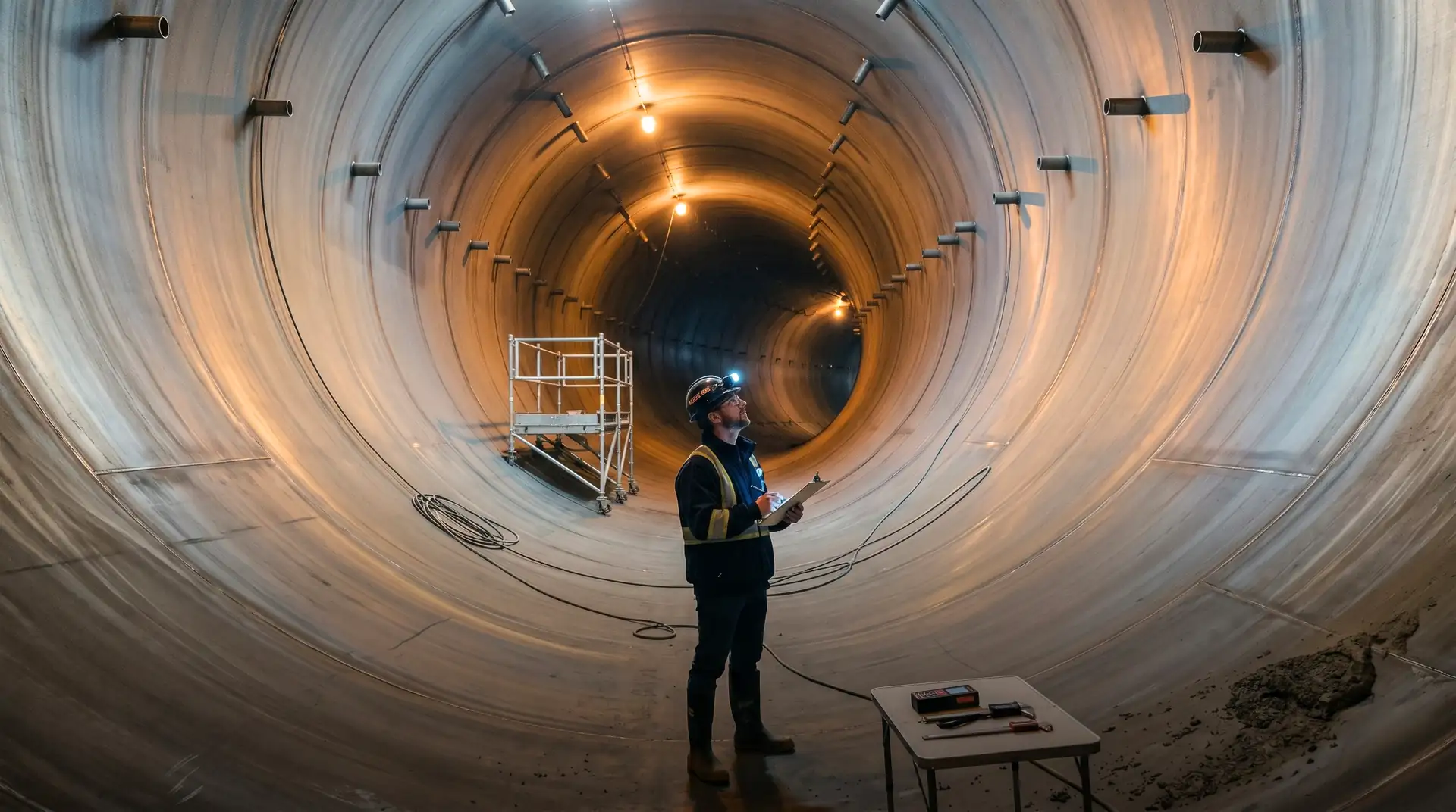
Transition Section
Between the intake and the penstock or tunnel, a concrete transition section changes the flow cross-section from the large, often rectangular intake opening to the smaller, circular penstock section. This transition must be hydrodynamically smooth, with no abrupt changes in section or surface irregularities.
Concrete Requirements by Component
First-Stage Concrete (Parent Concrete)
First-stage concrete forms the bulk of the intake structure. Its requirements are similar to the dam body structural concrete but with enhanced surface finish on hydraulic surfaces.
| Parameter | Typical Specification |
|---|---|
| Compressive strength (28 days) | 30-35 MPa |
| Maximum aggregate size | 40-80 mm |
| Water-cementitious ratio | 0.40-0.45 |
| Slump | 50-75 mm |
| Surface tolerance (hydraulic faces) | Plus or minus 6 mm under 3 m straightedge |
| Cover to reinforcement | 75-100 mm (upstream face) |
| Minimum cement content | 320-360 kg/m³ |
Per IS 456:2000, the minimum cover for concrete exposed to severe environmental conditions is 45 mm. However, dam intake structures typically require 75 to 100 mm on the upstream face to provide additional protection against carbonation and chloride ingress over the 100-year design life.
Second-Stage Concrete (Metalwork Encasement)
Second-stage concrete is placed around embedded metalwork after the first-stage concrete has hardened. It is arguably the most technically demanding concrete placement on the entire project.
| Parameter | Typical Specification |
|---|---|
| Compressive strength (28 days) | 40-50 MPa |
| Maximum aggregate size | 10-12 mm |
| Water-cementitious ratio | 0.35-0.40 |
| Slump | 150-200 mm (or self-compacting) |
| Shrinkage | Non-shrink or shrinkage-compensating |
| Surface tolerance (gate groove) | Plus or minus 2 mm |
| Surface tolerance (seal seat) | Plus or minus 1-2 mm flatness |
The small aggregate size is dictated by the clearances between embedded steel elements. Gate guides, anchor bolts, reinforcing steel, and seal seat plates create congested zones where standard concrete with 40 mm aggregate simply cannot flow. The mix design must be fluid enough to fill every void, yet strong enough and dense enough to resist the hydraulic forces and abrasion that the gate imposes.
ACI PRC-304-00 provides guidance on placing concrete in congested sections, including techniques for working around embedded metalwork.
Non-Shrink Requirements
Shrinkage of second-stage concrete around embedded metalwork is a critical concern. If the concrete shrinks away from the steel, three problems result:
- Leakage paths. The gap between concrete and steel provides a seepage pathway that can corrode the embedded metalwork from within.
- Seal failure. The gate seal seats on the concrete surface. If the concrete shrinks and deforms, the seal surface is compromised, and the gate leaks.
- Load transfer. The concrete must transfer hydrostatic loads from the gate to the dam structure. Gaps at the concrete-steel interface reduce the effective bearing area.
To address shrinkage, second-stage concrete mixes typically incorporate one or more of the following:
- Shrinkage-compensating cement (per ASTM C845): an expansive cement that produces controlled expansion during curing, offsetting drying shrinkage.
- Non-shrink grout admixtures. Metallic or chemical expanding agents that produce restrained expansion.
- Low water-cementitious ratio. Reducing the free water content reduces the potential for drying shrinkage.
- Extended wet curing. A minimum of 14 days, to allow maximum hydration and minimise early drying.
How is embedded metalwork integrated with concrete placement?
Types of Embedded Metalwork
Dam intake structures typically contain the following embedded metalwork:
| Component | Material | Function |
|---|---|---|
| Gate guides | Stainless steel or carbon steel | Guide gate travel |
| Seal seats | Stainless steel plate | Provide sealing surface |
| Anchor bolts | High-strength carbon steel | Anchor metalwork to concrete |
| Trashrack guides | Stainless steel angles | Guide trashrack panels |
| Grout pipes | Mild steel | Enable contact grouting behind plates |
| Drain pipes | Mild steel or PVC | Collect seepage behind gate |
| Cooling pipes | Mild steel | Control thermal cracking (mass pours) |
| Instrumentation conduits | Mild steel or PVC | House monitoring instruments |
Coordination Process
The sequence of work for embedded metalwork installation and concrete placement is critical. Errors in this sequence are among the most expensive problems on dam projects because they are discovered late and are difficult to correct.
Step 1: Anchor bolt installation. Anchor bolts are set in first-stage concrete at positions determined by the mechanical design drawings. Position accuracy of plus or minus 3 mm in plan and plus or minus 5 mm in elevation is typical. Bolts must be protected during first-stage concrete placement.
Step 2: First-stage concrete placement and curing. The parent concrete is placed and cured, leaving pockets or recesses for the metalwork installation. The surfaces that will receive second-stage concrete must be roughened (to a minimum amplitude of 6 mm) to ensure bond.
Step 3: Survey verification. After the first-stage concrete has cured and undergone initial shrinkage (minimum 28 days), the anchor bolt positions are surveyed and compared against the design coordinates. Any deviations must be documented and, if outside tolerance, corrective action must be taken before metalwork installation.
Step 4: Metalwork installation. Gate guides, seal seats, and other embedded components are installed on the anchor bolts. Each component is adjusted to its design position using shims, wedges, and nuts. The adjustment must achieve the required alignment tolerance (typically plus or minus 2 mm over the full height of the gate).
Step 5: Pre-pour survey. Before second-stage concrete is placed, a final survey confirms that all metalwork is within tolerance. This survey is a hold point: concrete placement cannot proceed until the survey is approved by the designer and the owner’s engineer.
Step 6: Second-stage concrete placement. The non-shrink, high-strength concrete is placed around the metalwork. Vibration must be sufficient to fill all voids but not so aggressive that it displaces the metalwork from its surveyed position. Where vibrator access is limited, self-compacting concrete (SCC) may be specified.
Step 7: Post-pour survey. After the second-stage concrete has hardened, the metalwork positions are surveyed again to confirm that concrete placement has not displaced them. Any movement exceeding the tolerance requires remedial action, which can range from grinding the concrete surface to chipping out and re-pouring.
Common Coordination Failures
- Anchor bolts in wrong position. If discovered after concrete has hardened, correction requires core drilling and epoxy-grouted replacement bolts. Delay: 1 to 4 weeks per gate slot.
- Metalwork displaced during concreting. Excessive vibration or concrete pressure can push gate guides out of alignment. Prevention: use temporary bracing and monitor alignment during pour.
- Poor bond between first-stage and second-stage concrete. If the first-stage surface is not properly prepared (cleaned, roughened, saturated surface dry), the second-stage concrete can debond, creating a leakage path. Per IS 3370 (Part 2):2021, construction joint preparation for water-retaining structures requires surface roughening and cleaning.
- Insufficient cover over embedded steel. Minimum cover of 50 mm over embedded steel is typically specified, mirroring the IS 456 reinforcement-cover provisions for severe exposure. Corrosion of embedded steel due to insufficient cover or porous concrete is a long-term durability risk.
What surface quality do intake hydraulic surfaces require?
Flow Velocity and Surface Quality Relationship
The surface quality requirements for intake concrete are determined by the flow velocity. Higher velocities demand smoother surfaces.
| Flow Velocity (m/s) | Surface Tolerance | Risk if Exceeded |
|---|---|---|
| Less than 3 | Plus or minus 12 mm | Minor head loss |
| 3-7 | Plus or minus 6 mm | Moderate head loss, turbulence |
| 7-12 | Plus or minus 3 mm | Cavitation risk at irregularities |
| Greater than 12 | Plus or minus 2 mm | Active cavitation, progressive erosion |
For dam intakes, flow velocities typically range from 2 to 8 m/s during normal operation but can be significantly higher during flood discharge through sluice gates. The concrete surface specification must be based on the maximum expected velocity, not the average operating velocity.
Surface Finishing Techniques
Achieving tight surface tolerances on formed concrete surfaces requires specific techniques:
- Steel formwork. Essential for gate slots and seal seats. Plywood forms cannot maintain the dimensional accuracy required.
- Grinding. After formwork removal, surfaces can be ground using diamond cup grinders to achieve flatness tolerances of plus or minus 1 to 2 mm. Grinding removes the surface laitance layer, exposing harder paste and aggregate.
- Epoxy filling. Surface voids (bug holes) that exceed the specification limit are filled with epoxy mortar, then ground flush with the surrounding surface.
- Template checking. Gate slot dimensions are verified using precision templates that match the gate profile. Any deviation from the template profile exceeding 2 mm requires correction.
Abrasion and Erosion Protection
Intake structures on Himalayan rivers face severe abrasion from sediment-laden flow. The abrasion is most severe:
- At the bell mouth entrance, where flow accelerates
- On the invert (floor) of the intake, where sediment settles and is dragged by flow
- At transitions where the flow changes direction or velocity
- Around trashrack slots where flow concentration increases local velocity
Abrasion-Resistant Concrete Specification
For intake surfaces exposed to sediment-laden flow, the concrete specification should include:
| Parameter | Requirement |
|---|---|
| Compressive strength | 40-50 MPa at 28 days |
| Maximum aggregate size | 20-25 mm |
| Aggregate hardness | Los Angeles abrasion less than 25% |
| Silica fume | 5-8% of cementitious |
| Water-cementitious ratio | 0.38 maximum |
| Abrasion resistance (ASTM C1138) | Less than 3% mass loss at 72 hours |
Alternative Protection Systems
For intakes on rivers with exceptionally high sediment loads, concrete alone may not provide adequate long-term abrasion resistance. Alternative protection systems include:
- Granite or basalt block lining. Natural stone blocks with abrasion resistance superior to concrete, mortared to the concrete substrate.
- Steel plate lining. Stainless steel or abrasion-resistant steel plate (AR400/AR500) welded to embedded anchors and grouted behind.
- Polymer concrete overlay. Resin-based concrete with superior abrasion resistance, applied in layers of 10 to 25 mm.
- Ceramic tile lining. Alumina ceramic tiles bonded with epoxy, providing exceptional hardness (Mohs 9) but limited impact resistance.
The choice depends on the severity of abrasion, the accessibility for future repair, and the project budget. ACI PRC-207.6-17 (Report on the Erosion of Concrete in Hydraulic Structures) reviews the abrasion-erosion, cavitation, and chemical-attack mechanisms and the protection systems used on dam hydraulic surfaces.
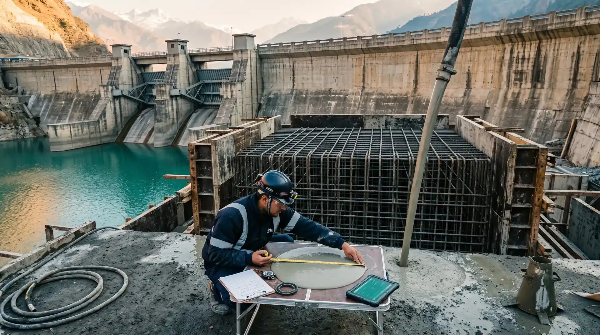
How is intake and gate slot concrete quality verified?
Dimensional Verification for Gate Slots
Gate slot dimensional verification is a multi-stage QA/QC process that extends from first-stage concrete through metalwork installation to second-stage concrete completion.
| Stage | Verification Method | Tolerance |
|---|---|---|
| Anchor bolt position (as-placed) | Total station survey | Plus or minus 3 mm |
| First-stage concrete surface | Straightedge + dial gauge | Plus or minus 6 mm |
| Metalwork alignment (pre-pour) | Total station + template | Plus or minus 2 mm |
| Second-stage concrete surface | Straightedge + dial gauge | Plus or minus 2 mm |
| Gate travel test (dry run) | Gate operation test | Smooth travel, no binding |
| Seal seat flatness | Feeler gauge + straightedge | Plus or minus 1 mm |
The final gate travel test is the ultimate verification. The gate is lowered through the full travel range without water. Any binding, scraping, or resistance indicates dimensional non-conformance that must be corrected before the reservoir fills.
Concrete Quality Testing
Beyond the standard cube tests per IS 516 (Part 1/Sec 1):2021, intake and gate slot concrete quality verification should include:
- Core testing. Cores drilled from critical zones verify that in-situ strength matches specimen strength. Differences exceeding 15% indicate compaction or curing deficiencies.
- Ultrasonic pulse velocity (UPV). Per IS 516 Part 5/Sec 1:2018 (which superseded the withdrawn IS 13311 Part 1:1992), UPV testing identifies internal voids and honeycombing, particularly in congested zones around embedded metalwork where visual inspection is impossible.
- Permeability testing. Water permeability tests per IS 3085 on cores from the intake confirm that the concrete will resist water penetration under the design head.
- Pull-out testing of anchor bolts. A percentage of anchor bolts (typically 5%) are tested to verify that the embedment achieves the design pull-out capacity.
Lessons from Practice
Congestion Management
The single most common construction problem in intake and gate slot concrete is honeycombing due to reinforcement and metalwork congestion. The solution lies in planning:
- Clearance analysis. Before concreting, verify that vibrator access is available at every point. If a 50 mm vibrator cannot reach a zone, either modify the reinforcement layout or specify SCC.
- Pour sequence. For complex gate slots, divide the pour into stages that allow vibration of each layer before the next is placed. Document the pour sequence on the method statement and enforce it on site.
- Trial pours. For the first gate slot on a project, conduct a trial pour using a full-scale mockup of the metalwork and reinforcement. This reveals congestion issues before they occur in the actual structure.
Thermal Cracking in Intake Structures
Large intake structures with wall thicknesses exceeding 2 metres are susceptible to thermal cracking during cement hydration. Thermal cracks that intersect gate slots or seal seats create leakage paths that compromise gate performance.
Prevention measures include limiting the cement content by using supplementary cementitious materials (fly ash, GGBS), limiting the lift height to 1.5 to 2.0 metres, pre-cooling the concrete using chilled water and ice, and installing embedded cooling pipes in thick sections. ACI PRC-207.1-21 (Mass Concrete Guide) provides guidance on thermal control of mass concrete, and its recommendations apply to intake structures as they do to the dam body.
Conclusion
Intake structures and gate slots represent the intersection of civil engineering and mechanical engineering within a dam project. The concrete must satisfy both disciplines: it must be strong, durable, and waterproof (civil requirements), and it must be dimensionally precise, smooth, and compatible with embedded metalwork (mechanical requirements).
The key to success is coordination. The concrete technologist, the structural designer, the mechanical designer, and the construction supervisor must work together from the design stage through to commissioning. The concrete mix must be designed to flow around congested metalwork. The formwork must maintain precision tolerances. The placement sequence must ensure full compaction without displacing the metalwork. And the quality verification must confirm every dimension before the reservoir fills.
When this coordination works, the intake structure and its gates function smoothly and reliably for the life of the dam. When it fails, the project faces costly rework, delayed commissioning, and ongoing operational problems that are extremely difficult to correct after the reservoir is impounded.