Diagnosing a concrete crack on a hydropower dam construction site is a 5-step field workflow: observe, classify, diagnose, assess severity, decide response. It takes 60 to 90 minutes for a typical crack pattern and produces a defensible decision among five possible responses (accept, monitor, repair, investigate, or halt). Anchored on ACI 224R-01, ACI 224.1R-07, and IS 456:2000 Clause 35.3.2 crack-width limits.
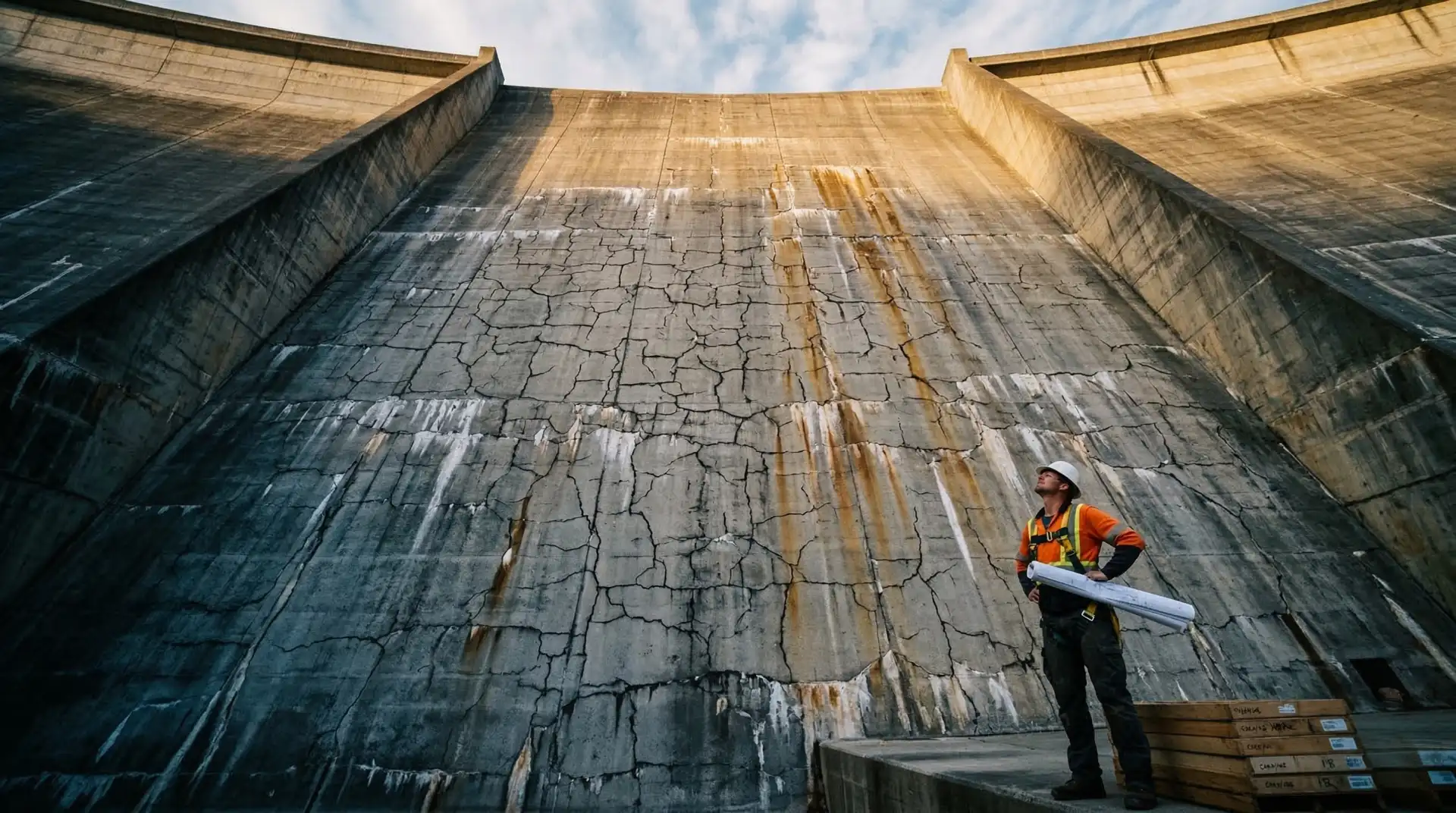
Every concrete dam programme produces cracks. Some are predicted by the design. Some are tolerated by the specification. Some are warnings that something is wrong. The owner’s engineer’s job is not to be surprised by the existence of cracks. The job is to distinguish, fast, between cracks that the structure will live with for 100 years and cracks that the structure will fail because of.
This is the field workflow used to make that distinction. It runs in five steps: observe, classify, diagnose, assess severity, decide response. It takes 60 to 90 minutes for a typical crack pattern on a dam site. The decision it produces guides the next 20 to 50 years of the structure’s life. The workflow draws on ACI 224R-01 (Control of Cracking in Concrete Structures), ACI 224.1R-07 (Causes, Evaluation, and Repair of Cracks in Concrete Structures), the IS 456:2000 crack-width framework, the IS 516 Part 5 non-destructive testing of concrete series (which superseded the withdrawn IS 13311 family in 2018-2020), and the USBR Concrete Manual, refined by leadership experience across more than 4,000 MW of hydroelectric concrete placement. It pairs naturally with PCCI’s accept-repair-reject decision framework, which takes the diagnosed crack to its disposition decision.
What is the wrong way to diagnose a crack on a dam?
Before the workflow, a word on the failure mode it is built to prevent. A QC engineer arrives on site, looks at the crack, and says: “thermal.” The contractor’s project manager nods. The crack is sealed with non-shrink mortar by the end of the shift. Three years later, the same crack reopens, this time with calcium deposits on the surface and a damp halo on the downstream face. By then no one remembers when the crack was first observed, what the placement temperature history was, or whether the original diagnosis of “thermal” was even correct. The structure will live with the crack, but the project file no longer holds the evidence to defend the decision.
This sequence is the failure mode. The 5-step workflow is designed to prevent each of its three errors: undocumented evidence, single-cause assumption, and unverified diagnosis under schedule pressure.
Step 1: Observe
Document the crack carefully before doing anything else. The information available at first sight is the richest you will ever have. Patching, sealing, even cleaning the crack destroys evidence. The Observe step is what the workflow protects.
What to record
Pattern. Longitudinal (running parallel to a structural axis), transverse (perpendicular), diagonal (at an angle to axes), or map (random network of fine cracks). The pattern is the first clue to the cause.
Location. The structural element (dam body, foundation, gallery wall, intake, spillway, powerhouse, training wall), the position within the element (lift face, vertical face, intersection of two surfaces, near an embedded item, at a contraction joint), and the elevation. Cracks in mass concrete dam construction often correlate strongly with location relative to restraint.
Orientation. Vertical, horizontal, or at a specific angle. Combined with pattern, orientation often reveals the stress field that produced the crack.
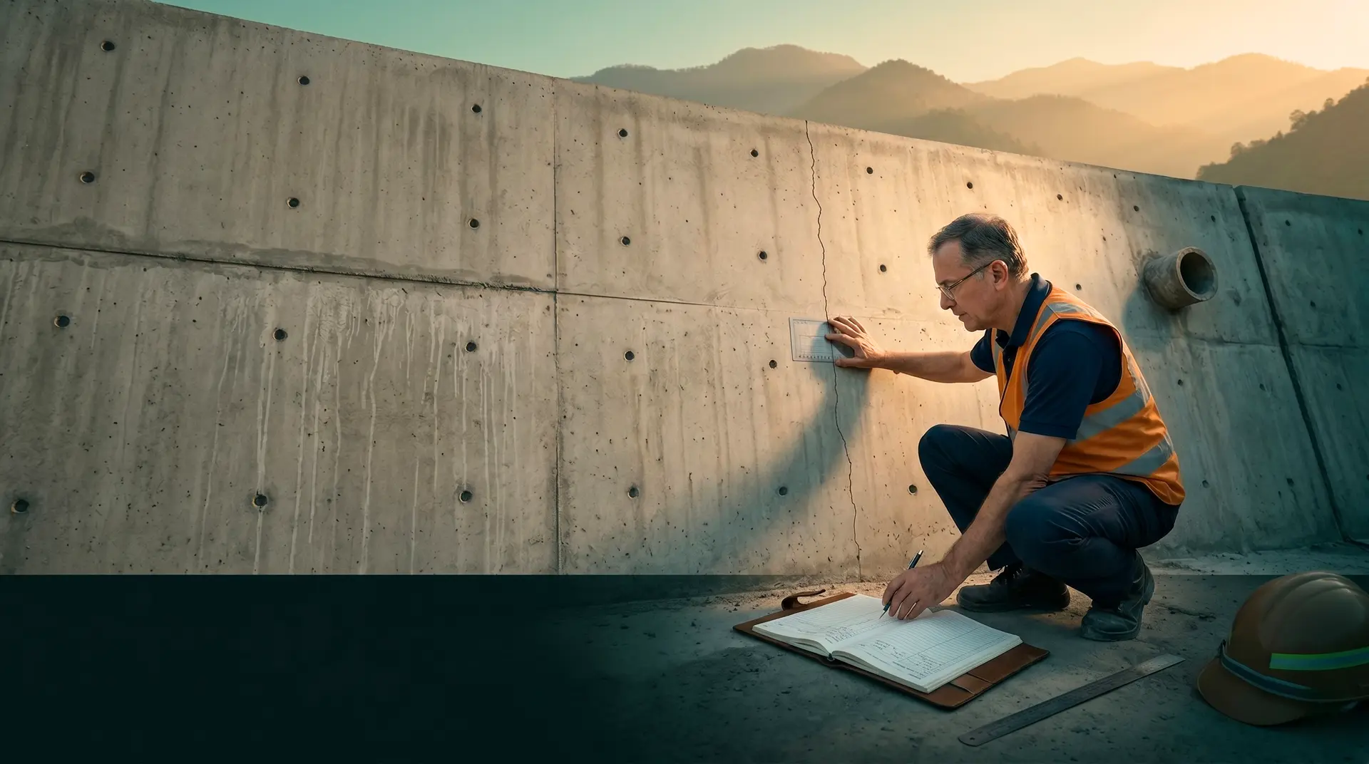
Width. Measured at multiple points along the crack length using a crack comparator card or a 40x magnification crack microscope. Record the maximum, the average, and the locations of maximum and minimum width.
Depth. Estimated from surface signs (a deep through-thickness crack often shows the same width on both faces of a member; a shallow surface crack does not). Confirmed by ultrasonic pulse velocity (UPV) test per IS 516 Part 5/Sec 1:2018 (Non-destructive Testing of Concrete: Ultrasonic Pulse Velocity), which superseded the withdrawn IS 13311 Part 1:1992, or by core extraction when justified.
Dynamics. Active or dormant. An active crack changes width with temperature, load, or time. A dormant crack does not. Dynamics are determined by repeat measurement at marked points over days or weeks, or by installation of a crack monitoring gauge (DEMEC, dial-gauge, vibrating-wire crack meter).
Surface signs. Calcium deposits (efflorescence) indicate active seepage. Rust staining indicates reinforcement corrosion in the crack path. Dust patterns or sediment accumulation in the crack mouth indicate the crack has been dormant for some time. Wet edges or weeping indicate active seepage.
Surrounding concrete condition. A crack in otherwise sound concrete is a localised event. A crack surrounded by other cracks, or by spalling, scaling, or surface deterioration, is a symptom of a wider problem.
What instruments to carry
Six items in the owner’s engineer’s site bag:
- Crack comparator card (graduated transparent plastic, 0.05 to 1.0 mm graduations) for rapid field width measurement.
- Portable crack width microscope, 40× magnification with depth indication scale.
- Measuring tape for length and location mapping.
- Digital camera with macro lens and a known-scale reference (steel rule or coin) for photographic documentation.
- Handheld ultrasonic pulse velocity tester per IS 516 Part 5/Sec 1:2018 for crack-depth and surrounding-concrete-quality assessment.
- Structured field notebook with a crack-log template: date, time, observer, project area, crack ID, all the parameters above, and space for sketches.
Optional additions: handheld rebound hammer per IS 516 Part 5/Sec 4:2020 (which superseded IS 13311 Part 2:1992) for surface hardness, and crack monitoring gauges for active-crack tracking.
What to photograph
At minimum: an overview shot showing the crack in context of the structural element, a close-up against scale showing width clearly, a perpendicular shot showing crack depth signs (or both faces if through-thickness), and detail shots of any unusual features (deposits, staining, intersections with other features).
Every photograph must include a date stamp and a known-scale reference. A photograph without scale is decoration. A photograph with scale is evidence.
Step 2: Classify
With observations recorded, classify the crack against the practitioner taxonomy. Eight categories cover the cracks that appear during dam construction. Each has a typical pattern, timing, location, and width range.
1. Plastic shrinkage cracks
Timing: 30 minutes to 6 hours after placement; commonly visible within 24 to 72 hours of pour. Mechanism explained in ACI PRC-305-20 (Guide to Hot Weather Concreting).
Pattern: Short, parallel cracks on the exposed surface, often perpendicular to the prevailing wind direction. Random pattern is also possible. Each crack is typically 50 to 200 mm long. They do not extend to the edges of the placement.
Location: Exposed top surface of any concrete placement: powerhouse slab, spillway chute, dam crest, secondary works. They do not occur on formed vertical faces because plastic shrinkage requires evaporation from a free surface.
Width range: 0.1 to 0.5 mm at the surface, narrowing rapidly with depth. Surface only, typically less than 25 mm deep.
Mechanism: Evaporation rate from the fresh surface exceeds the rate at which bleeding water rises. Capillary tension builds in the still-plastic concrete and pulls the surface apart. The threshold rate is approximately 1.0 kg/m²/h per ACI PRC-305-20.
2. Plastic settlement cracks
Timing: 1 to 3 hours after placement.
Pattern: Cracks aligned with embedded items below the surface: reinforcement bars, conduits, embedded plates. The crack appears directly above the obstruction.
Location: Anywhere with embedded items close to the top surface. Common in heavily reinforced sections such as dam crest, intake structures, gallery walls, powerhouse foundations.
Width range: 0.1 to 1.0 mm at the surface.
Mechanism: Fresh concrete settles after placement as bleed water rises. Concrete above an embedded item cannot settle freely; concrete around the item settles more. The differential settlement opens a crack above the obstruction.
3. Thermal contraction cracks
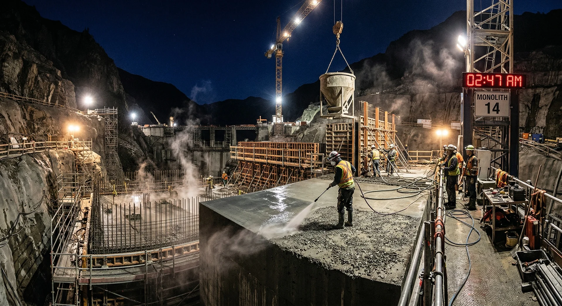
Timing: Days to two weeks after placement. The exact timing depends on element thickness, ambient temperature, and cooling rate. In mass concrete dam construction, the first one to two weeks after placement is the critical period.
Pattern: Through-thickness or near-through-thickness cracks, often vertical on a dam body or transverse to the long axis of a lift. They may follow restraint geometry, particularly when the new lift is restrained by the previously cast lift below.
Location: Mass concrete dam body, large foundation blocks, heavy raft foundations, powerhouse mass concrete walls and floors.
Width range: 0.2 to 2.0 mm depending on the temperature differential and the degree of restraint.
Mechanism: Concrete generates heat during cement hydration, reaching peak temperature 1 to 7 days after placement. As the concrete cools toward ambient, it contracts. If the contraction is restrained (by foundation, by reinforcement, by the cooler outer skin of the concrete itself), tensile stresses develop. When the tensile stress exceeds the concrete’s tensile capacity at that early age, the concrete cracks. Research shows that about 80 percent of cracks in mass concrete are caused by restrained deformation rather than external load.
4. Drying shrinkage cracks
Timing: Weeks to months after placement. Majority of drying shrinkage occurs in the first 28 days but visible cracking emerges over weeks to several months. Approximately 50 percent of total drying shrinkage occurs in the first 2 months; approximately 80 percent in the first year. Full process can continue at diminishing rate for 2 to 5 years.
Pattern: Random map pattern of fine cracks on exposed surfaces. Also called pattern cracking or crazing. Cracks are typically not deep.
Location: Exposed concrete surfaces, particularly thin sections, slabs, walls. Less common in dam body mass concrete because the moisture loss to ambient is slow at depth.
Width range: Typically 0.05 to 0.3 mm, surface or near-surface only.
Mechanism: As concrete loses moisture to the ambient atmosphere, it shrinks. If the shrinkage is restrained (by reinforcement, by subgrade, by adjacent older concrete), tensile stress develops and cracks form. Unlike plastic shrinkage, drying shrinkage cracking develops in hardened concrete, not in fresh concrete.
5. Alkali-aggregate reaction (AAR) cracks
Timing: Months to years after placement. The reaction is slow and requires moisture; visible cracking may not appear until 5 to 20 years.
Pattern: Map cracking on exposed surfaces, often with calcium-silica-gel deposits visible at the crack mouths under magnification. Cracks may be accompanied by surface popouts or pattern darkening.
Location: Anywhere with reactive aggregates and continuous moisture. In dam construction, AAR is most commonly observed in dam bodies, intake structures, and any concrete with continuous water contact.
Width range: 0.2 to several millimetres over time.
Mechanism: The alkali content in cement reacts with reactive silica in aggregates in the presence of moisture, producing an expansive gel that opens cracks from within the concrete. Documented in ACI 224.1R-07, PCCI’s dedicated article on AAR, and IS 2386 Part VII guidance on aggregate reactivity testing.
6. Structural cracks
Timing: Under load, designed or undesigned. May appear immediately upon load application, or progressively under cyclic loading.
Pattern: Follows stress trajectories. In a flexural member, cracks are perpendicular to the tension face. In a shear-loaded zone, cracks are diagonal at approximately 45 degrees to the axis. In compression zones, cracks are parallel to the loading axis (spalling).
Location: Anywhere subjected to load. Often at points of stress concentration: corners of openings, supports, change of section, embedded inserts under load.
Width range: Highly variable, from 0.05 mm for designed flexural cracks at service load, to several millimetres for distressed structural cracks.
Mechanism: Applied load exceeds the concrete’s load-carrying capacity, either as designed (flexural cracks under service load are designed to occur and are limited by reinforcement) or undesigned (concrete failing under unanticipated load, settlement, or imposed deformation).
7. Restraint cracks (early-age)
Timing: First 7 to 30 days after placement.
Pattern: Vertical cracks in walls or vertical members, often equally spaced along the length. The spacing is related to the restraint geometry and the wall height.
Location: Walls cast on rigid foundations, walls cast against previously hardened concrete, heavily reinforced sections where the steel restrains contraction.
Width range: 0.1 to 0.5 mm, often through-thickness.
Mechanism: A combination of thermal contraction and drying shrinkage, restrained by the foundation, adjacent concrete, or embedded reinforcement. Discussed in ACI 207.2R (Report on Thermal and Volume Change Effects on Cracking of Mass Concrete). See also PCCI’s thermal control in mass concrete for the underlying heat-management framework that prevents this class of crack.
8. Construction-defect cracks
Timing: Visible at form stripping or shortly after.
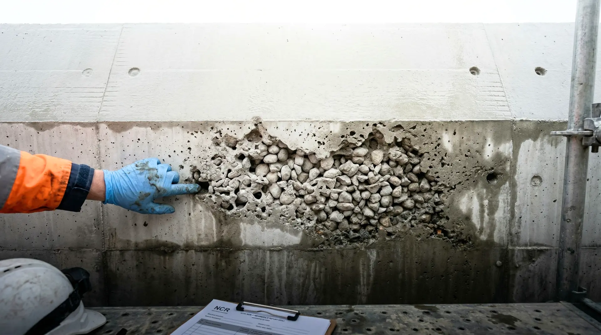
Pattern: Variable, depending on the underlying defect. Cold joints produce a planar horizontal or sloped crack at the join between two pours. Honeycombing-related cracks appear at form corners and lift faces. Formwork-related cracks follow form panel boundaries or appear where the form was disturbed during placement.
Location: At construction interfaces: lift joints, contraction joints, formwork panel joins, embedment penetrations.
Width range: Variable.
Mechanism: Workmanship failure or process failure during construction, not a property of the hardened concrete itself. Discussed in PCCI’s cold joint and honeycombing articles.
Step 3: Diagnose
With the classification provisionally made, the diagnosis step verifies the classification against the evidence and discriminates between candidate causes. A single observed crack often has more than one candidate cause; the diagnostician’s job is to test each candidate against the evidence and pick the best-supported one (or, when multiple causes combine, name all of them).
The discriminator framework
Five discriminators do most of the work:
Timing. When did the crack first appear (or first get noticed)? The 8-category taxonomy is largely organised by timing. Plastic shrinkage is hours; thermal is days to weeks; drying shrinkage is weeks to months; AAR is months to years.
Geometry. Does the crack pattern match the candidate cause’s expected pattern? Plastic shrinkage = short parallel cracks at surface. Thermal contraction = through-thickness cracks following restraint. Drying shrinkage = map pattern. AAR = map with gel. Structural = follows stress trajectory.
Environmental conditions at the relevant time. For plastic shrinkage, the evaporation rate at placement determines whether plastic shrinkage was even possible. For thermal contraction, the placement temperature, ambient cooling rate, and lift thickness determine the thermal history. For AAR, the moisture availability and aggregate reactivity are the gates.
Mix and material composition. Cement content, fly ash percentage, aggregate type, water-to-cementitious ratio, admixture dosing. Each candidate cause has mix-composition dependencies. High cement content increases heat of hydration and therefore thermal cracking risk. Reactive aggregates with high cement alkali content increase AAR risk. Excessive water content increases drying shrinkage. Low water increases plastic shrinkage risk if curing is inadequate.
Location relative to restraint. For restraint cracking, the geometry of the foundation, the embedded reinforcement, and the adjacent older concrete determines where cracks will form. A crack at the wall-foundation interface in the first month is restraint-related until proven otherwise.
How to apply the discriminators
Take the observed crack. List the 2 to 3 most likely classifications based on initial observation. For each candidate, walk through the discriminators:
- Does the timing match the candidate’s typical window?
- Does the geometry match the candidate’s typical pattern?
- Were the environmental conditions at the relevant time consistent with the candidate’s mechanism?
- Is the mix composition consistent with the candidate?
- Is the location consistent with the candidate’s typical occurrence?
The candidate that scores best across all five is the working diagnosis. If two candidates score similarly, both are recorded and the next step (severity assessment) is performed against the more conservative one.
Common diagnosis errors
Single-cause assumption. Most cracks in mass concrete have more than one contributing cause. A vertical wall crack at 14 days may be both thermal (early-age temperature differential) and restraint (foundation restraint). Naming only one cause leads to an incomplete remediation strategy.
Confirmation bias. The diagnostician decides the answer in step 1 and uses the rest of the workflow to confirm it. The discipline of running all candidates against all discriminators counteracts this.
Skipping the timing question. Timing is the strongest single discriminator. A diagnosis that does not anchor on timing is weak. Always ask: when was this crack first observed, and what is the elapsed time from placement?
Generic “thermal.” “Thermal” is not a diagnosis. A diagnosis is “thermal contraction at the lift-2 / lift-3 interface, driven by 8°C core-surface differential that exceeded the 6°C limit imposed by mix composition under the lift schedule.” Specificity is what makes the diagnosis defensible.
Step 4: Assess Severity
A crack has been observed, classified, and diagnosed. Now: how bad is it? Severity is assessed along three axes: structural impact, durability impact, and watertightness impact. Each axis is scored independently. The overall severity is the worst of the three.
Axis 1: Structural impact
Question: Does the crack reduce the structural capacity below the design requirement?
Method: Locate the crack on the structural drawings. Identify the load path it interrupts (flexural, shear, axial). Run the design check against the cracked section assumption. If the cracked-section capacity meets the design load, structural impact is low. If it does not, structural impact is high.
Common cases:
- A 0.2 mm flexural crack in an under-reinforced flexural element at design load: low impact (this is expected behaviour, accounted for in design).
- A 0.5 mm shear crack at 45 degrees in a non-reinforced zone: medium to high impact.
- A through-thickness crack in a dam body subject to hydrostatic load: depends on crack orientation; transverse cracks have very different implications from longitudinal ones.
For mass concrete dam bodies, structural impact assessment requires the original design engineer or an equivalent reanalysis. The owner’s engineer’s role is to flag the concern, not to redesign.
Axis 2: Durability impact
Question: Does the crack expose reinforcement or aggressive zones of the concrete to ingress of water, chlorides, sulphates, or CO₂?
Method: Compare the measured crack width against the IS 456 or fib Model Code crack-width limits for the exposure class of the structural element.
IS 456:2000 limits (Clause 35.3.2, Table 15):
| Exposure | Description | Crack width limit |
|---|---|---|
| Mild | Protected from severe weather | 0.3 mm |
| Moderate | Continuous moisture or soil/groundwater contact | 0.2 mm |
| Severe / Very Severe / Extreme | Marine, chloride, sulphate, abrasion, freeze-thaw | 0.1 mm |
fib Model Code / Eurocode 2 limits:
| Exposure | Limit |
|---|---|
| X0, XC1 to XC4 (no chloride risk) | 0.3 mm |
| XD1 to XD2, XS1 to XS3 (chloride, marine) | Decompression (no permanent tension cracks) |
For dam concrete, the upstream face is typically Severe / Very Severe (continuous water contact, potentially with dissolved sulphates), giving a 0.1 mm limit. The downstream face is typically Moderate, giving 0.2 mm. Interior galleries and dry zones are Mild, giving 0.3 mm.
A crack wider than the limit for its exposure class is durability-significant. A crack within the limit is durability-acceptable, though it may still warrant monitoring.
Axis 3: Watertightness impact
Question: Does the crack create a seepage path?
Method: Locate the crack relative to the water-bearing or pressure-bearing zones of the structure. Assess whether it is through-thickness or surface-only. Assess whether it is active (changing width) or dormant. Inspect for visible seepage, calcium deposits, or staining.
Common cases:
- A surface-only crack on the downstream face of a dam body: low watertightness impact.
- A through-thickness crack on the upstream face of a dam body intersecting the pool elevation: high impact.
- A crack at a contraction joint, parallel to the joint: depends on joint waterstop integrity.
- A horizontal crack at a lift joint near the upstream face: high impact (typical seepage path in mass concrete dams).
For hydropower dam projects where watertightness is a primary functional requirement, the watertightness axis often dominates. The Mangdechhu, Punatsangchhu-1, and Tala HEP projects all required watertightness performance demonstrated by reservoir filling, not just by crack width.
Combining the three axes
Score each axis as Low, Medium, or High. The overall severity is the worst of the three. A crack that is Low on structural, Low on durability, but High on watertightness is a High-severity crack and requires a High-severity response.
Step 5: Decide Response
Five possible responses, in escalating order of intervention.
Response A: Accept
When: Low on all three axes. The crack is within the durability limit for its exposure, has no structural significance, and creates no seepage path.
Action: Document the crack in the project’s crack register. Photograph against scale. Mark on the as-built drawings. No further action required.
Common examples: Hairline plastic shrinkage cracks on a powerhouse slab that will be covered by an additional wearing course. Drying shrinkage map cracking on an interior gallery wall in a Mild-exposure zone. Plastic settlement cracks above a single reinforcement bar in a non-load-bearing element.
Response B: Monitor
When: Medium on at least one axis, with uncertainty about whether the crack is active.
Action: Mark the crack at multiple points with permanent paint markers and fixed-position references. Install crack monitoring gauges if the crack is suspected active (DEMEC studs, dial-gauge readers, vibrating-wire crack meters). Measure at scheduled intervals (typically weekly for the first month, then monthly, then quarterly). Log all measurements in the crack register. Set thresholds for escalation: if the crack grows by more than X mm or moves outside its monitoring band, the response escalates to Investigate or Repair.
Common examples: A thermal contraction crack at 14 days that is at the durability limit and may continue to open as cooling progresses. A restraint crack at a wall-foundation interface that may stabilise or may continue to develop.
Response C: Repair
When: Medium to High on durability or watertightness, with the cause understood and the structural impact low.
Action: Select a repair method appropriate to the cause and the severity. Common methods:
- Surface sealing for cracks within the durability limit but exposed to mild attack: brushed-on penetrating sealer, methacrylate, or silicone-based water repellent.
- Crack injection for active or seepage-significant cracks of 0.1 to 1.0 mm width: low-viscosity epoxy resin (for structural restoration) or polyurethane chemical grout (for sealing seepage).
- Cement grouting for wider cracks (over 1 mm) and seepage-significant joints: cement-based grout under controlled pressure.
- Surface mortar repair for shallow, contained defects: non-shrink repair mortar, applied per ACI 224.1R-07 guidance on repair techniques.
- Structural repair for cracks with structural implications: stitching, external post-tensioning, anchorage, or section replacement.
For mass concrete dams, the choice between epoxy and polyurethane injection often depends on whether the crack is active (in which case polyurethane is preferred because it remains flexible) or dormant (in which case epoxy provides structural restoration of bond).
Response D: Investigate further
When: The diagnosis is uncertain, the severity is potentially high, or the consequences of an incorrect decision are significant.
Action: Commission targeted investigation. Common investigations:
- NDT campaign: UPV at multiple locations, impact-echo for depth, half-cell potential for reinforcement corrosion. Per IS 516 Part 5/Sec 1:2018 (UPV) and Sec 4:2020 (Rebound Hammer).
- Core extraction: A 100 mm or 150 mm diameter core through the crack, examined visually and tested for compressive strength, density, chloride profile, carbonation depth, and (if AAR suspected) petrographic analysis.
- Petrographic analysis: Microscopic examination of thin sections for AAR, freeze-thaw damage, sulphate attack, or cement paste deterioration.
- Structural reanalysis: Re-run of the design check under the cracked-section assumption, often with site-specific load measurements.
- Long-term monitoring: Extended instrumentation with crack gauges, embedded strain gauges, or distributed fibre-optic sensors for cracks that warrant tracking for years.
The investigation is commissioned by the owner’s engineer with the project owner’s approval. Results inform the eventual response (Accept, Monitor, Repair, or Halt).
Response E: Halt and report
When: The crack is structurally significant, the watertightness impact is high and the next construction phase would conceal it, or the cause is unknown and proceeding could compound the defect.
Action: Issue a notice to halt adjacent work. Escalate to the project owner with a written report (within 24 hours) summarising the observation, the diagnosis, the severity assessment, and the recommended next steps. The halt remains in force until the project owner, advised by the owner’s engineer and any necessary experts, decides on the resolution.
Halts are rare. Across PCCI’s leadership portfolio including Tala (1,020 MW), Mangdechhu (720 MW), and Punatsangchhu-1 (1,200 MW), the situations that justified halts were ones where the alternative was building the next lift on top of a defect that would have been impossible to assess once concealed. The halt option must be visibly on the table during every severity assessment, even when the eventual decision is Accept or Monitor. The visibility is what prevents schedule pressure from silently overriding engineering judgment.
What are the most common crack diagnostic mistakes on a dam site?
Five mistakes recur in field crack diagnosis across hydropower dam programmes:
Mistake 1: Diagnosing by photograph alone. A photograph captures pattern and width but not depth, dynamics, surrounding context, or surface condition. Walking the crack with a microscope and a UPV tester reveals what the photograph cannot.
Mistake 2: Single-cause assumption. Most cracks have multiple contributing causes. A wall crack at 14 days may be both thermal and restraint. Naming only one cause leads to a remediation strategy that addresses one mechanism and leaves the other to recur.
Mistake 3: Treating all cracks the same. Severity varies enormously. A 0.05 mm crazing pattern on an interior wall and a 1.5 mm through-thickness crack at the upstream face of a dam body are not the same problem. The 3-axis severity assessment (structural, durability, watertightness) is what differentiates them.
Mistake 4: Skipping the timing question. Timing is the strongest single diagnostic clue. A diagnosis that does not include “first observed at X days after placement” is weak.
Mistake 5: Accepting generic diagnoses under schedule pressure. “Thermal” is not a diagnosis. “Thermal contraction at the lift-2 / lift-3 interface, driven by 8°C core-surface differential measured by embedded thermocouples 4 to 8 in lift 2” is a diagnosis. The discipline to demand specificity is what separates an owner’s engineer’s diagnosis from a contractor’s QC engineer’s summary.
How does the crack diagnosis workflow integrate with the project quality system?
The 5-step workflow is not a standalone exercise. It feeds three documents in the project quality system:
The crack register. Every diagnosed crack is logged with date, location, classification, diagnosis, severity, and response decision. The register is a living document maintained by the QA/QC system and audited by the owner’s engineer.
The Non-Conformance Report (NCR). Cracks with severity Medium or higher trigger an NCR. The NCR carries root cause, corrective action, preventive action, and closeout verification. PCCI’s 12-defect article covers the broader NCR-worthy defect categories that often surface as cracks.
The as-built record. Cracks of severity Medium or higher are recorded on the as-built drawings, with classification, diagnosis, and repair (if performed) noted. This is the document that will be consulted 20 to 50 years later when the dam is inspected for service-life extension or rehabilitation. The DRIP Phase II programme administered by the Central Water Commission regularly encounters dams where the original crack records are absent, complicating the tender specifications for rehabilitation that follow.
Closing
The 5-step diagnostic workflow takes 60 to 90 minutes for a typical crack pattern on a hydropower dam construction site. The decision it produces is reviewed by the project owner, recorded in the crack register, and lives in the project’s as-built record for the structure’s design life of 100 years.
The workflow does not eliminate cracks. Cracks happen in mass concrete; some are inevitable and some are designed for. The workflow’s job is to ensure that every crack the structure carries is one whose nature and severity are known, whose cause has been diagnosed against the evidence, and whose response was the right one given the evidence.
PCCI’s Construction Troubleshooting & RCA service and Independent Review / Owner’s Engineer service provide this discipline on hydropower dam programmes across India, Bhutan, and Nepal. If your project is producing cracks faster than your engineers can diagnose them, or if a specific crack pattern is concerning enough to warrant independent review, the conversation begins with a site walk, the crack register, and the placement records for the affected lifts.